39 troubleshooting the mos90, 310 using the calibrator, 9 troubleshooting the mos90 -7 – Snorkel LX41 Electric-sn4022+ User Manual
Page 77: When a flash error occurs -7, 10 using the calibrator -7, Mos90, 10 u
Section 3 - Troubleshooting
Troubleshooting the MOS90
067448-003 LX31/LX41 Electric Work Platform
Page 3-7
3-9 T
ROUBLESHOOTING
THE
MOS90
Important basics applicable to the motor control unit.
• The MOS90 has a green diagnostics L.E.D. in the front panel.
• The green L.E.D. will turn on and shine continuously when the MOS90 is powered up and working cor-
rectly.
• The green L.E.D. will be off if no power is supplied to the MOS90.
• The green L.E.D. will flash a sequence of flashes if the MOS90 is damaged or is receiving an improper
signal. An explanation of the flash sequences "flash faults" is shown on the following pages.
• The MOS90 is high temperature protected by "thermal cutback". The cutback operates between 80°C
(176°F) and 90°C (194°F). Powered functions will gradually operate slower and slower until 90°C
(194°F). The MOS90 will shut down at 90°C (194°F). Continued operation at high temperature will
damage the MOS90.
• The MOS90 is low voltage protected by "low voltage cutout". The MOS90 shuts down at 14.0 VDC.
Powered functions suddenly stop. When input voltage goes above 14.0 VDC turns back on.
W
H E N
A
F
L A S H
E
R R O R
O C C U R S
S
TEP
1. Disconnect the 17 pin connector from the MOS90. Wait Five (5) seconds and plug it back in again. If
the flash error repeats go to step Two (2). If the green L.E.D. lights up and stays on continuously - operate
machine. Note which functions are being used when problem repeats itself.
S
TEP
2. Disconnect the 17 pin connector from the MOS90. Connect pin Six (6) to a fused battery supply (14.0
VDC minimum) and observe the green L.E.D. If flash error stays, replace MOS90. If green L.E.D. lights up
and remains on continuously, check wiring.
NOTE:
NOTE: Troubleshoot the possible cause of the flash error before replacing the MOS90, for example an Eight (8)
flash error will cure itself when the MOS90 cools down.
3-10 U
SING
THE
C
ALIBRATOR
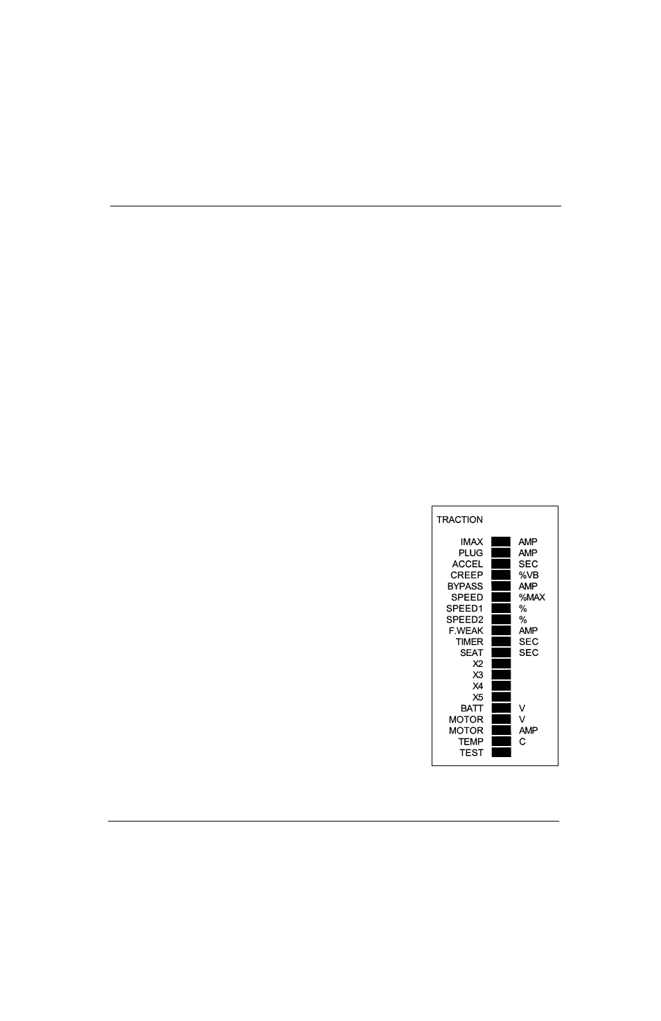
Figure 3-1: MOS90 Calibrator LED Segments
The calibrator has 20 L.E.D. segments marked as shown.
The values which should be expected when checking the machine are
shown on the following page.
There are three buttons on the calibrator:
increment, marked +
decrement, marked -
select
When select is pressed, each L.E.D. will light in sequence until the
select button is released. Each setting can be incremented or decre-
mented using the + or - buttons when the adjacent L.E.D. is lit.
When "Test" L.E.D. is lit, the state of the MOS90 inputs is displayed.
The first input displayed is the accelerator which can vary from 0-
100%. When the + button is pressed once the switch Input 1 is dis-
played. This will be seen as "1.0P" until the switch Input voltage
changes. "1.CL" will then be displayed. This is repeated for all the
switch inputs.
When BATTV, MOTORV, MOTORA and TEMPC are selected, the con-
troller shows their values. When BATTV is selected and the "+" button
is held in, the highest voltage that the MOS90 has recorded will be dis-
played. When TEMPC is selected and the "+" button is held in, the
highest temperature that the MOS90 has recorded will be displayed.
The "-" button will display the lowest values.
When the MOS90 is first powered up, the recorded minutes of run time
is displayed. The "+" button displays thousands of hours and the "-"
button displays hundreds of hours. When the MOS90 is pulsing (being used) run time is being incremented
and stored. The "dot" in the time display is blinking when MOS90 is being used, steady when idle.