Adjusting the height limit switch – MBW CG200 User Manual
Page 33
31
ADJUSTING THE HEIGHT LIMIT SWITCH:
1. The limit switch cuts power to the appropriate solenoid when the Automatic
Height Control lifts the rear wheel to an adjustable set point. This keeps the rear
wheel in contact with the ground at all times to maintain stability and traction.
2. Plug the limit switch pigtail into the limit switch cable on the Paver main unit. Use
the extension cable (#11447) if required.
3. The paver must be completely adjusted and ready to pour for a given concrete
mold. Loosen the 1/4" bolt holding the limit switch in place. Slide the switch
down until the wheel actuator contacts sensor bracket, continue sliding the
switch down until the switch contact snap is heard. Raise the switch until the
contact snap is heard again, then lower the switch down an additional 1/4" to
1/2" and tighten the bolt.
4. Test the limit switch position by placing the paver on a flat slab (concrete or asĆ
phalt) and lowering mold (manual control). The bottom edge of the mold
should be above the slab approximately 1/8" to 1/4". Mark the location of the
limit switch on cylinder.
5. The limit switch will stop the bottom edge of the mold from traveling below the
bottom edge of the rear tire. This will prevent the mold from dragging on the
ground and also maintain solid traction on the near wheel next to mold.
6. The limit switch height may have to be fine tuned depending on base stability.
Example: on loose base you may have to lower the limit switch approximately
1/4" to 1/2" to maintain better wheel traction.
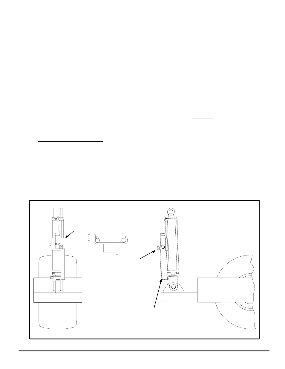
BRACKET MUST
HIT ROLLER AND
GO PAST LIMIT
SWITCH. IF
BRACKET HITS
LIMIT SWITCH
BEND BRACKET
OUT, BUT MAKE
SURE BRACKET
WILL STILL CONĆ
TACT ROLLER.
BRACKET MUST FIT AROUND
RODS ON CYLINDER AND BOLT
MUST BE TIGHTENED DOWN
PAST CENTER OF ROD.
SENSOR
BRACKET