Automatic steering sensor adjustments – MBW CG200 User Manual
Page 30
28
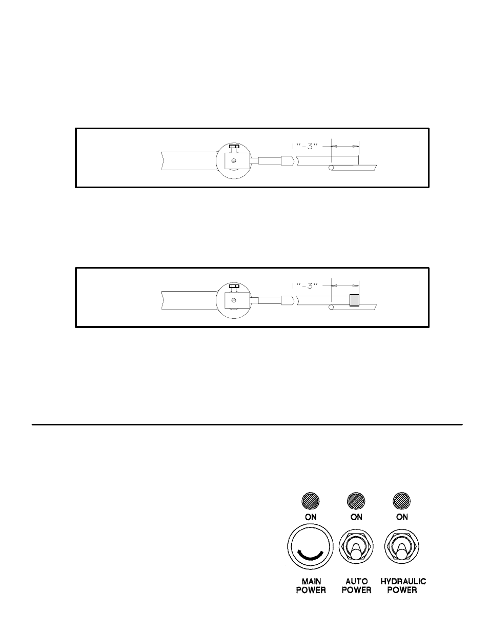
6. Front height sensor: Install sensor with potentiometer shaft facing forward. If not
previously done, remove counterbalance weight from one of the three wands
that are the same length. Replace it with 1/4-20 x 1/2 Hex Head Bolt. Install
wand in a horizontal position. Adjust sensor horizontally until string line is
approximately 1" to 3" inside end of wand. Adjust sensor vertically until wand
is roughly parallel to the grade. Adjust sensor potentiometer shaft so screw drivĆ
er slot is horizontal. Tighten wand bolt to secure wand to sensor.
7. Rear height sensor: Install sensor with potentiometer shaft facing forward.
Install wand in roughly a horizontal position. Adjust sensor horizontally until
string line is approximately 1" to 3" inside end of wand. Adjust sensor vertically
until wand is roughly parallel to the grade. Adjust sensor potentiometer shaft so
screw driver slot is horizontal. Tighten wand bolt to secure wand to sensor.
8. Check each wand to ensure that the wand base does not bind on the sensor
face. Connect sensor plugs to appropriate sensor cable on the main unit. The
height sensor cable is marked #3. The rear stearing sensor cable is marked #4
and has a single cable tie near the end. Extension cords are provided with the
sensor kit for the rear steering and height sensors.
AUTOMATIC STEERING SENSOR ADJUSTMENTS:
1. All switches off, FNR to neutral,
steering sensor selector to manual
and Height Pour-Manual-Grade
to Manual. Turn Main Power on and
Auto power on.