Attaching hopper – MBW CG200 User Manual
Page 21
19
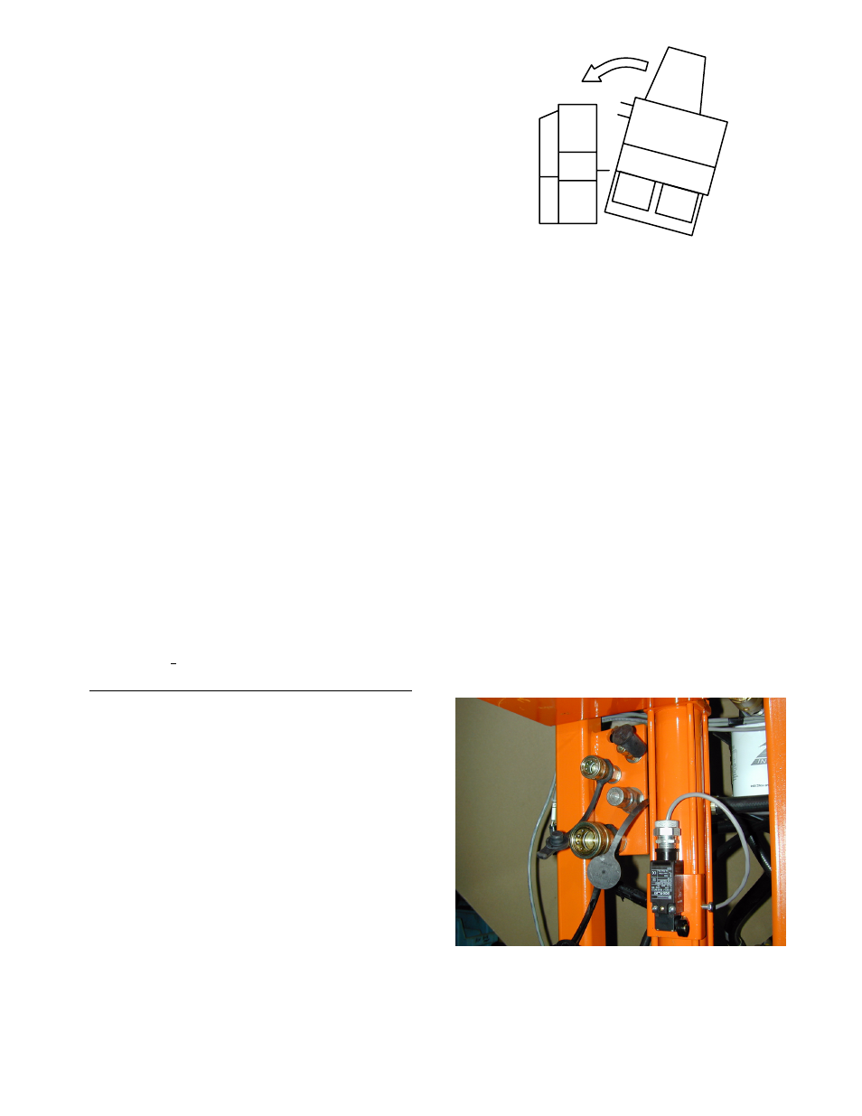
ATTACHING HOPPER:
1. Position the hopper unit level on
the ground. Back off the three hopĆ
per joining nuts. (Two on main unit,
one on hopper.)
2. Lower the Main unit so that the joinĆ
ing studs and mating slots are
approximately the same height
and back the Main unit up to the
Hopper unit at an angle.
3. Continue backing until the rear stud begins to engage. Cut the front wheel hard
right and continue backing until front studs engage. Tighten the nuts.
4. When using a hopper without the Side Drive Unit, flip the Side Drive Unit switch
to Detached". (Transfers auto-height control to center cylinder.)
5. With hoppers (24" and wider) using the Side Drive Unit, flip the Side Drive Unit
switch to Attached". (Transfers auto-height control to side drive unit cylinder.)
6. When not using the Side Drive Unit or the optional right rear drive wheel, the
Rear Drive switches (left or right) must be off. If the Rear Drive switch is left on,
the machine will not move.
7. When using the Side Drive Unit or the optional right rear drive wheel, the Rear
Drive switch (left or right) may be in one of two positions:
1. ON: drive is on and drives with the
front wheel.
2. OFF: drive is off and free wheels.
8. Connect hydraulic hoses as reĆ
quired.
NOTE: with the 12" hopper attached
S The side drive unit switch must be
switched to the detached position.
S The left drive wheel must be switch
off.
S The #3 or unused vibrator must be
turned off completely
S If either the left drive wheel or unĆ
used vibrator is switched on" the
hydraulic system will dead head (a
restricted flow of hydraulic fluid that
will kill the engine).