Technical data sheet, Connector description – Class1 118711 - TPG+ Governor - 118710 EXTERNAL User Manual
Page 30
FORM-ENG-0018 REV A 05-27-03
PAGE
29
OF 30
TECHNICAL DATA SHEET
DATE
4/9/2009
PRODUCT GROUP
THROTTLE CONTROL
P/N
118710
REV
1.00
607 NW 27th Ave
Ocala, FL 34475
Ph: 352-629-5020 or 1-800-533-3569
Fax : 352-629-2902 or 1-800-520-3473
PRODUCT
TOTAL PRESSURE GOVERNOR PLUS (TPG+)
BY
AMS
Manual P/N 118711
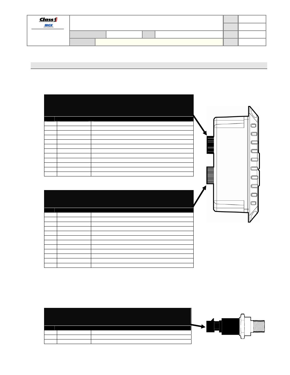
8. Connector Description
8.1. TPG+
connectors
The module has two connectors and the following definitions apply:
Mating connector:
Deutsch DT06-12SB BLACK
Mating sockets:
Deutsch 0462-201-16141
Gold mating sockets: Deutsch 0462-201-1631
Wedge lock: W12S Recommended wire gage: 16-20 AWG
PIN
CIRCUIT
DESCRIPTION
1 SUPPLY
(+)
(
INPUT
)
– battery voltage
(+9VDC…+32VDC)
2 CAN
HIGH
(
DATA
)
– SAE J1939 CAN 2.0B, 250Kbits/s *
3 CAN
SHIELD (
DATA
)
– SAE J1939 CAN 2.0B, 250Kbits/s *
4 ----
----
5 Sensor
GND
(
OUTPUT
) – Intake pressure ground
6 Sensor
REF
(
OUTPUT
) – Intake pressure supply
(+5VDC)
7 Sensor
SIGNAL (
INPUT
)
– Intake pressure signal
(+0.5VDC to +4.5VDC)
8 ----
----
9 ----
----
10 ALARM
(-)
(
OUTPUT
) – alarm active
(ground polarity, 250mA)
11 CAN
LOW
(
DATA
)
– SAE J1939 CAN 2.0B, 250Kbits/s *
12 SUPPLY
(-)
(
INPUT
)
– battery ground
*
Gold sockets recommended for CAN connections.
Mating connector:
Deutsch DT06-12SA GRAY
Mating sockets:
Deutsch 0462-201-16141
Wedge lock: W12S Recommended wire gage: 16-20 AWG
PIN
CIRCUIT
DESCRIPTION
1
ENG REF (+)
(INPUT)
– analog signal reference
(+5VDC) *
2 THROT
INTLK (
INPUT
)
– throttle ready interlock
(positive polarity)
3 HI
IDLE
(
INPUT
)
– high idle enable
(positive polarity)
4 ----
----
5 Sensor
GND
(
OUTPUT
) – Discharge pressure ground
6 Sensor
REF
(
OUTPUT
) – Discharge pressure supply
(+5VDC)
7 Sensor
SIGNAL (
INPUT
)
– Discharge pressure signal
(+0.5VDC to +4.5VDC)
8 ENG
SIGNAL
(OUTPUT)
– analog signal control
(+0.5VDC to +4.5VDC) *
9
ENG REF (-)
(INPUT)
– analog signal reference
(ground) *
10 PUMP
INTLK
(
INPUT
)
– pump engaged interlock
(positive polarity)
12 RELAY
COM
(
INPUT
)
– remote throttle reference
(ground polarity) *
12 RELAY
N.O.
(
OUTPUT
) – remote throttle activate
(ground polarity) *
*
These pins and wires are available with the analog signal harness (p/n 117683)
8.2. Pressure sensor connector
The pressure sensors (intake and discharge) have one connector and the following definitions apply:
Mating connector: Packard 12078090
Mating sockets:
Packard 12089290
Recommended wire gage: 16-20 AWG
PIN
CIRCUIT
DESCRIPTION
A SUPPLY
(-)
(
INPUT
)
– pressure sensor ground
B SUPPLY
(+)
(
INPUT
)
– pressure sensor supply
(+5VDC)
C Signal
(
OUTPUT
) – pressure sensor signal
(+0.5VDC to +4.5VDC)