Ddec wiring, Important, Ddec governor wiring – Class1 107490 - UNI-Governor 107396 107269 software v 6 00 User Manual
Page 29
28
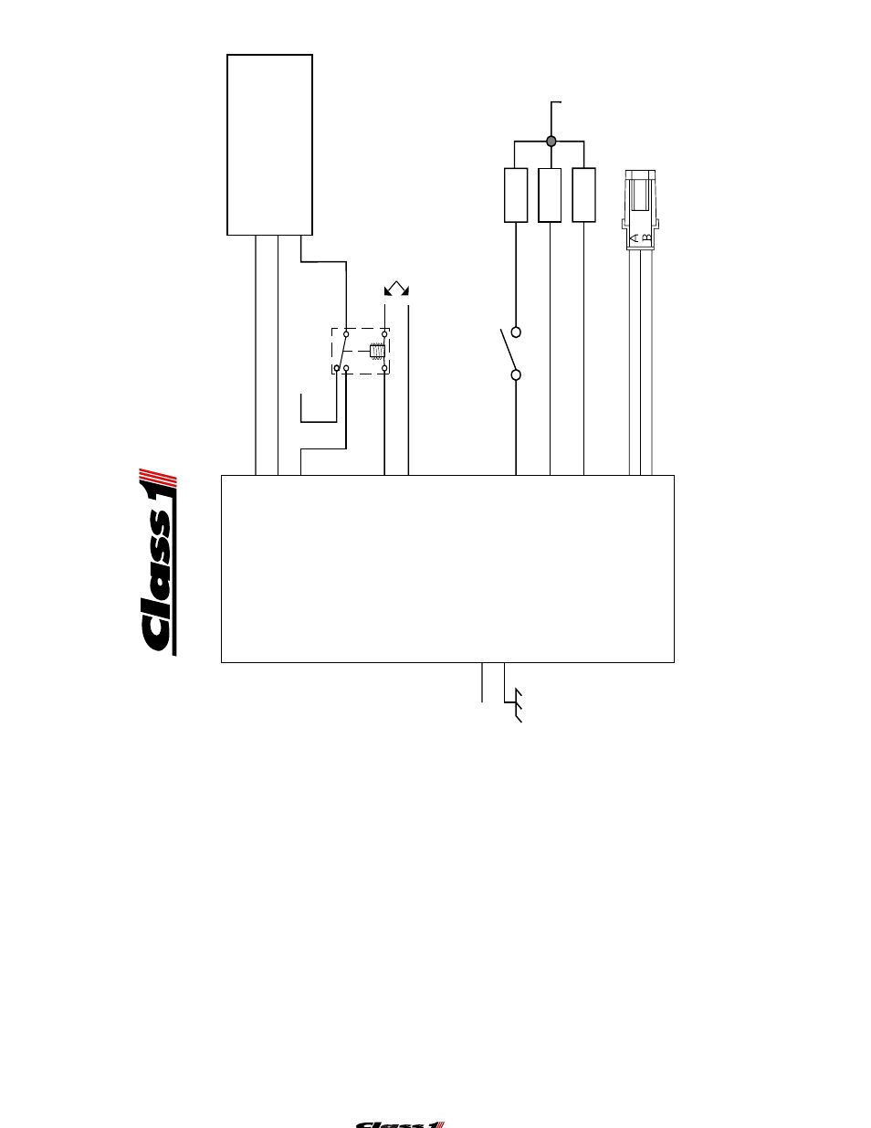
DDEC Wiring
Pressure Governor
Reference Voltage C12-1
Reference Ground C12-9
Control Signal C12-8
DDECWiring
A-3 916 +5VDC
C-3 952 Throttle Return
D-1 510 VSG Remote Throttle
Important
: This governor version incorporates the Engine 5 Volt and Ground References.
IT WILL NOT OPERATE without these circuits wired as shown.
Any questions should be directed to Class1 Support at 1-800-533-3569
DDEC Governor Wiring
Connector
DT06-4S
T
erminal
Sockets
Position
Wire Color
Description
1
RED
+ 12 VDC
2
Black
Ground
3
Plug
NC
4
Plug
NC
Connector
DT06-12S
T
erminal
Sockets
Position
Wire Color
Description
1
Red
ECM +5 VDC
2
White
OEM Interlock
3
White
High Idle
4
Brown
NC
5
Black
Sensor Ground
6
Red
Sensor V
oltage
7
White
Sensor Signal
8
Y
ellow
ECM Control Signal
9
Black
ECM Signal Ground
10
White
PT
O Interlock
1
1
Orange
Enable Input
12
Blue
Enable Output
4-1 12 VDC
4-2 Ground
12 VDC
Pump
Engaged
OEM
Interlocks
FAST
IDLE
High Idle C12-3
Throttle Ready C12-2
Pump Engaged C12-10
Throttle
Ready
ECU Power
High Idle Switch
Sensor Ground C12-5
Sensor V
oltage C12-6
Sensor Signal C12-7
A
Black
Ground
B Red
+5 VDC
C White
Signal
T
ransducer
Connector
525 Ground
Relay Out C12-12
Relay In C12-11
Opposite Polarities