Class1 107490 - UNI-Governor 107396 107269 software v 6 00 User Manual
Page 14
13
C:\manuals\Uni-Gov-V6-107490
3
Governor Message Center displays SENSOR
The governor will display SENSOR whenever the transducer input is less than 0.3 VDC. This input is at
pin 7 of the governor 12 pin connector. You can measure this voltage in either of two ways. A voltmeter
back probing pin 7 or on the governor Message Center.
Enter the password:
INC IDLE IDLE IDLE IDLE IDLE INC IDLE
The message center will display XDC=x.xV where x.x is the voltage to one decimal place that is read at
pin 7.
There are 2 main requirements for the transducer to operate correctly.
1.
Five volts supplied from the governor at pin 6 to the transducer pin B.
2.
Ground supplied from the governor at pin 5 to the transducer pin A.
If either of these are missing, check the output at the governor and if present, check the wiring.
If both are present at the transducer, then with power on and the connector installed, back probe terminal
C of the transducer and check for 0.7 VDC. This is the zero pressure output of the transducer +- 0.1
VDC. If present, check the signal wire to the governor.
Note: There have been many cases of moisture and corrosion in the transducer connections causing
problems. Use a bright light and inspect the transducer and connector for visible moisture, corrosion
and/or mineral deposits. If present, this might be the reason for the SENSOR reading. There is a
removable seal on the round section of the transducer connector, ensure that it is still present. Check
under the wire weather seal for corrosion and moisture as well. If moisture or corrosion is present, clean
the contacts (the use of a moisture displacing chemical is recommended (WD40, CRC 5-56, etc.) and
check for signal voltage again.
Once SENSOR is displayed, the SENSOR message will not clear until power to the governor is re-
moved and reapplied even if the error is corrected.
4
Governor changes engine RPM but will oscillate when in RPM mode
This is usually attributable to the governor sending out a PWM signal when the engine requires an
analog signal. Check the V number for an ‘a’ or an ‘F’. An F indicates the governor is programmed for
CAT and an ‘a’ shows that there is a 12 VDC input on terminal 4 of the 12 pin connector. If this is not the
case then a poor ground at pin 9 or a fluctuating 5 volt supply at pin 1 needs to be investigated.
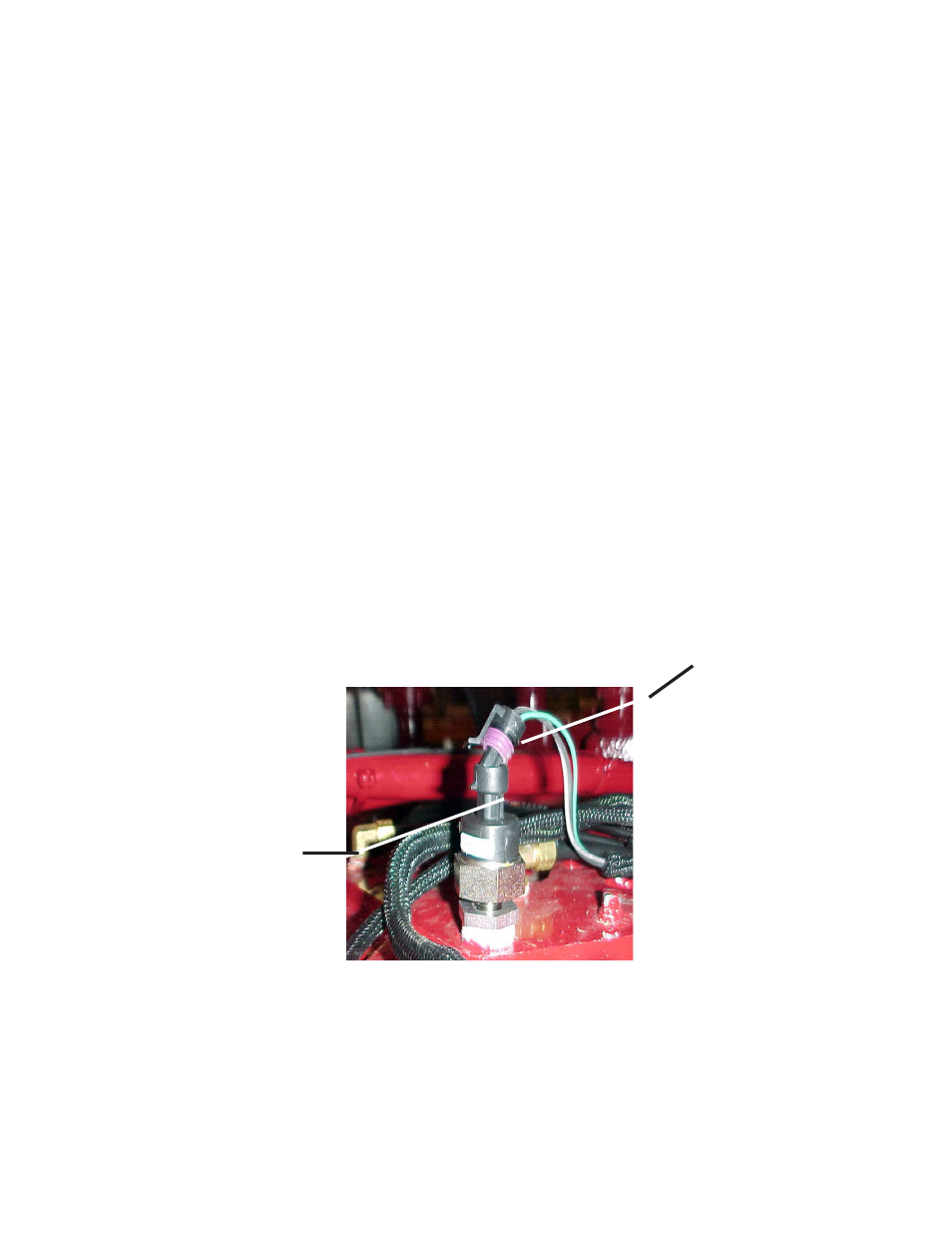
R
EMOVABLE
S
EAL
D
IELECTRIC
GREASE
CAN
BE
ADDED
TO
THE
SEALING
SUR
-
FACE
TO
ENSURE
A
BETTER
MOISTURE
BARRIER
.
C
HECK
THAT
THE
HARNESS
ISN
’
T
PULLED
TO
ONE
SIDE
DISTORTING
THE
WIRE
WEATHER
SEAL
. T
HIS
IS
ANOTHER
SOURCE
OF
M
OISTURE
I
NTRUSION
.