Installation – Class1 107490 - UNI-Governor 107396 107269 software v 6 00 User Manual
Page 20
19
C:\manuals\Uni-Gov-V6-107490
Installation
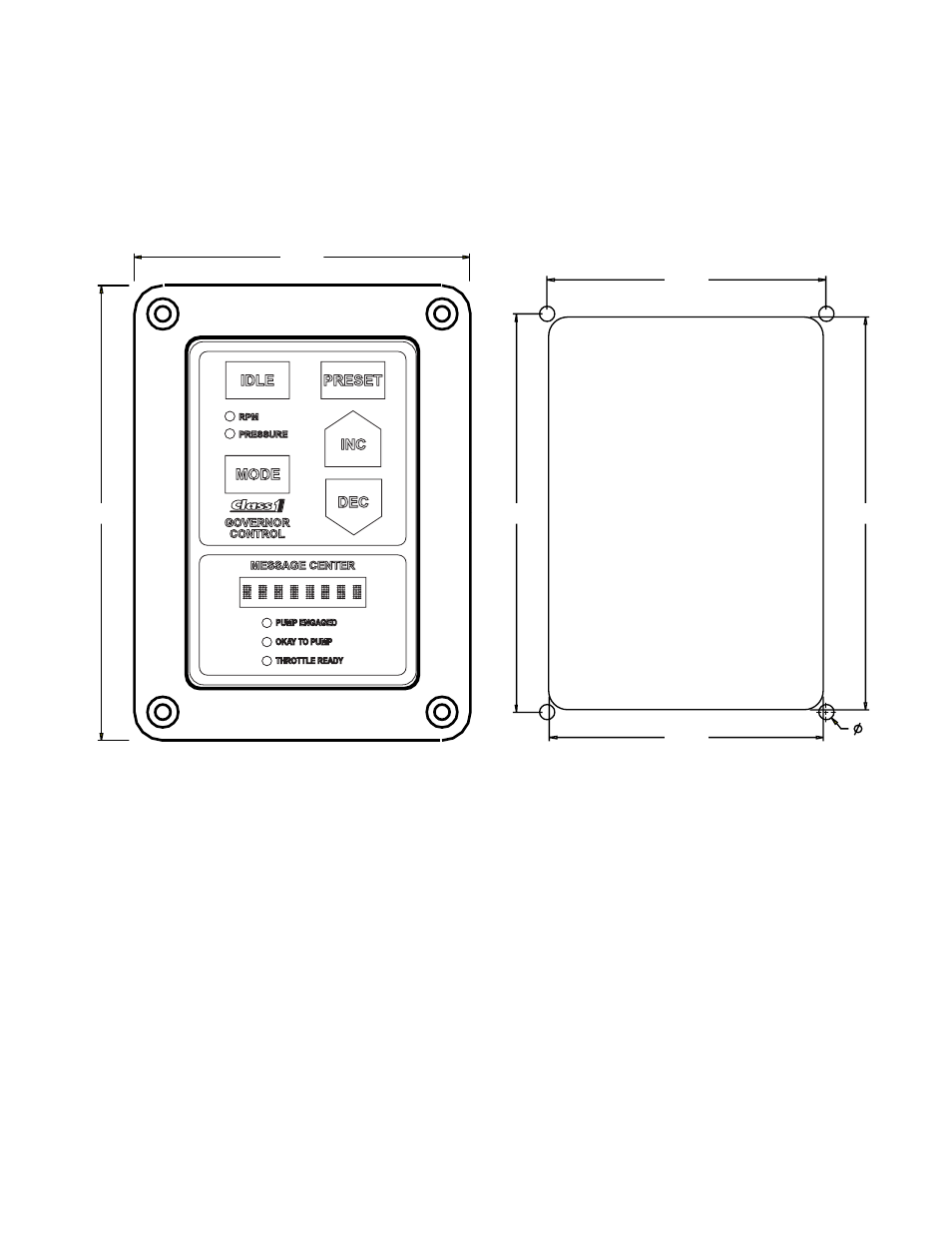
Control Module
The control module requires a rectangular cutout as shown. The module is watertight and may be mounted in
any location on the operators panel.
Pressure Transducer
Locate the pressure transducer where it can read pump discharge pressure without turbulence. A ‘tee’ at the
Master Discharge Gauge would be a good location, this should also reduce vibration to the transducer. Threads
are 1/4 NPT and a sealant should be applied prior to installation. The transducer should be located in an area
with minimum turbulence. When tightening the transducer, apply torque to the 1-1/4” hex flange of the trans-
ducer, not the body. Every effort should be made to eliminate the chance for moisture entering the transducer
connector including immediate connection of the transducer harness connector after installation.
System Wiring
The pressure governor comes with wiring and connectors for installation.
Refer to the diagrams in the manual for specific input requirements.
Refer to the appropriate Engine Electronic Application and Installation Guide for information on engine electri-
cal interfacing and programming.
Installation
02817,1*+2/(6$1'
&87287',0(16,216