Self test, X x x 3 - x x 7 x x x - 4 x x 7 – Class1 107490 - UNI-Governor 107396 107269 software v 6 00 User Manual
Page 19
18
Self Test
POS-0
POS-1
POS-2
POS-3
POS-4
POS-5
POS-6
POS-7
x x x x x x x x
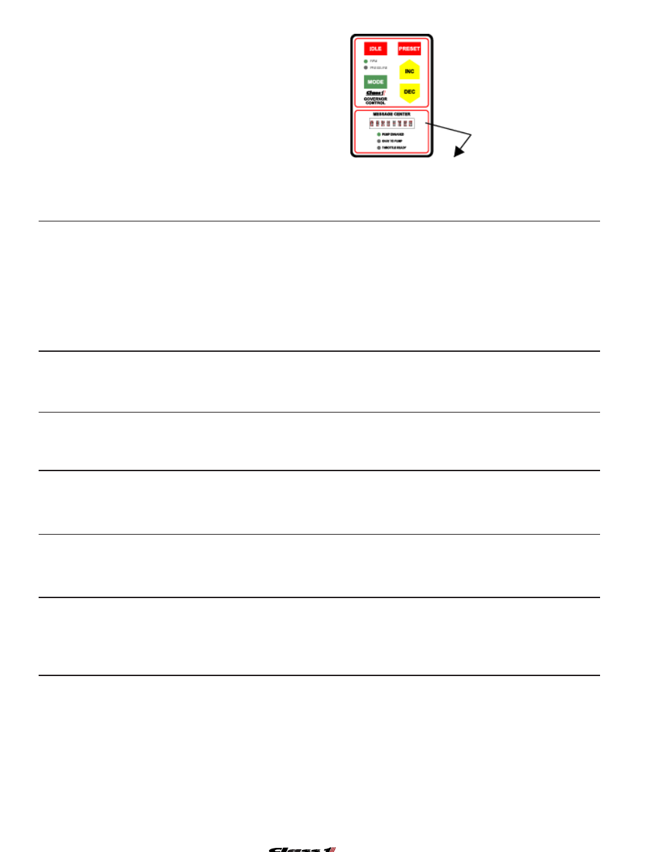
TEST SETUP
The apparatus should have the engine running at idle
with the transmission in neutral, the parking brake
applied and the pump should not be engaged.
Monitor the Message Center and note what is dis-
played. If type=ANA is displayed, it will be followed
by a voltage range. This range is very important for
diagnostics.
To exit the selftest, press IDLE and PRESET at the
same time.
POS-0 OEM Interlock
POS-1 PTO Interlock
POS-2 Switch Panel
POS-3 Analog Type
POS-4 PWM Type
POS-5 Transducer
POS-6 High Idle Input
POS-7 Internal Relay
Enter the Self Test by pressing in sequence:
IDLE INC IDLE INC IDLE INC IDLE INC
Below is a guide to the tests and at the bottom, a place to record your readings.
The Okay to Pump LED will begin flashing and the output type is checked. The Message Center will
display:
Type = ANA or Type = PWM
ANA will be followed by a voltage range, please note this range below.
After determining output type, the Message Center will normally look like one of these.
X X X
3 -
X X 7
X X X
- 4
X X 7
OEM Interlock Test POS-0
Release the Park Brake or Shift from Neutral
PTO Interlock Test
POS-1
Shift into Pump Gear
Shift to Back to Road Gear
Reapply the Parking Brake or shift back to Neutral
0
X X 3 - X X 7
0
1
X 3 - X X 7
Transducer 0 PSI test
POS-5
0 1 X 3 -
5
X 7
0 1 X 3 -
H
X 7
0 1 X 3 -
F
X 7
5 indicates normal 0 PSI
H indicates more than 0 PSI
F indicates failure.
Switch Panel Test
POS-2
(press each switch at least once, in any order)
0 1
u
3 - 5 x 7
0 1
p
3 - 5 x 7
0 1
2
3 - 5 x 7
High Idle Switch Test
POS-6
Engage the High Idle Switch if equipped.
0 1 2 3 - 5
6
7
0 1 2 3 - 5
X
7
A 6 indicates that the High Idle switch was recognized. X indicates that the switch was not seen, if High
Idle worked, then this would mean that the governor High Idle circuit is not being used.
1 indicates that the interlock input changed.
X indicates that the input has not changed.
0 indicates that the interlock input changed.
X indicates that the input has not changed.
At this point, all of the basic governor functions have been tested. If all sections passed, then the prob-
lem is likely not in the governor. You can press PRESET and IDLE at the same time to exit the Self Test.
Remove power from the governor. Press and hold the IDLE switch and reapply power to the governor.
A ‘V’ number will appear and remain as long as you continue to hold the IDLE switch.
Record the V number here:
A 2 indicates that all switches were recognized. X indicates at least one was missed.
__ __ __ __ __ __ __ __
0 1 2 3 4 5 6 7
Type = ANA ( ) Analog
PWM ( ) Pulse Width Modulated (CAT)
Analog ____.____ to ____.____ VDC
Enter your results here...
The 7 may or may not be shown depending on the condition of the interlocks.
__ __ __ __ __ __ __ __
V 6
.
0 x 4 4 4