AEM 30-3532 GM LS 24x Engines Layover User Manual
Page 21
Rev A, 2013/02/05
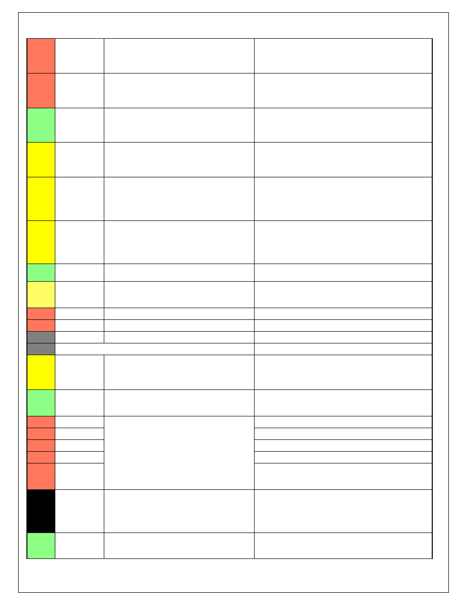
C2-31
AGND_2
Dedicated analog ground
Analog 0-5V sensor ground
C2-32
AGND_2
Dedicated analog ground
Analog 0-5V sensor ground
C2-33
Analog_In_20
12 bit A/D, 100K pullup to 5V
0-5V analog signal. Use +5V Out pins as power supply and
Sensor Ground pins as the low reference. Do not connect
signals referenced to +12V as this can permanently damage the
ECU.
C2-34
Analog_In_21
12 bit A/D, 100K pullup to 5V
0-5V analog signal. Use +5V Out pins as power supply and
Sensor Ground pins as the low reference. Do not connect
signals referenced to +12V as this can permanently damage the
ECU. See 3StepSwitch 1-axis table for setup.
C2-35
Analog_In_22
12 bit A/D, 100K pullup to 5V
0-5V analog signal. Use +5V Out pins as power supply and
Sensor Ground pins as the low reference. Do not connect
signals referenced to +12V as this can permanently damage the
ECU. See USBLoggingRequestIn channel for input state. See
Setup Wizard page USB Logging for configuration options.
C2-36
Analog_In_23
12 bit A/D, 100K pullup to 5V
0-5V analog signal. Use +5V Out pins as power supply and
Sensor Ground pins as the low reference. Do not connect
signals referenced to +12V as this can permanently damage the
ECU. See ChargeOutPress [kPa] channel for input state. See
Setup Wizard page Charge Out Pressure for calibration options.
C2-37
Digital_In_6
No pullup. Will work with TTL signals.
Input can be assigned to different pins. See Setup Wizard page
Input Function Assignments for input mapping options.
C2-38
Digital_In_7
No pullup. Will work with TTL signals.
See ClutchSwitch 1-axis table for setup options. Input can be
assigned to different pins. See Setup Wizard page Input
Function Assignments for input mapping options.
C2-39
Power Ground
Power Ground
Connect directly to battery ground
C2-40
Power Ground
Power Ground
Connect directly to battery ground
C2-41
CanH_Bout
Dedicated High Speed CAN Transceiver
Not used
C2-42
CanL_Bout
Dedicated High Speed CAN Transceiver
Not used
C2-43
LowsideSwitch
_8
Lowside switch, 4A max with internal flyback diode.
Inductive load should NOT have full time power.
Activates if any of the following flags are true:
OilPressProtectOut, LeanProtectOut, CoolantProtect. Output
can be assigned to other functions. See Setup Wizard page
LowSide Assignment Tables for additional options.
C2-44
LowsideSwitch
_7
Lowside switch, 4A max with internal flyback diode.
Inductive load should NOT have full time power.
See Spare GPO1 Basic Setup section of User GPIOs and PWM
Setup Wizard page LowSide Assignment Tables for additional
options.
C2-45
UEGO 2 VM
Bosch UEGO Controller
Virtual Ground signal. Connect to pin 5 of Bosch UEGO sensor.
C2-46
UEGO 2 UN
Nernst Voltage signal. Connect to pin 1 of Bosch UEGO sensor
C2-47
UEGO 2 IP
Pumping Current signal. Connect to pin 6 of Bosch UEGO sensor
C2-48
UEGO 2 IA
Trim Current signal. Connect to pin 2 of Bosch UEGO sensor
C2-49
UEGO 2 HEAT
Lowside switch for UEGO heater control. Connect to pin 4 of
Bosch UEGO sensor. NOTE that pin 3 of the Sensor is heater (+)
and must be power by a fused/switched 12V supply.
C2-50
+12V_R8C_CP
U
Dedicated power management CPU
Optional full time battery power. MUST be powered before the
ignition switch input is triggered (See C1-65).
C2-51
Coil 7
25 mA max source current
0-5V Falling edge fire. DO NOT connect directly to coil primary.
Must use an ignitor OR CDI that accepts a FALLING edge fire
signal.