Infinity ecu pinout – AEM 30-3532 GM LS 24x Engines Layover User Manual
Page 16
Rev A, 2013/02/05
Infinity ECU Pinout
Infinity - 10, P/N 30-7100/01
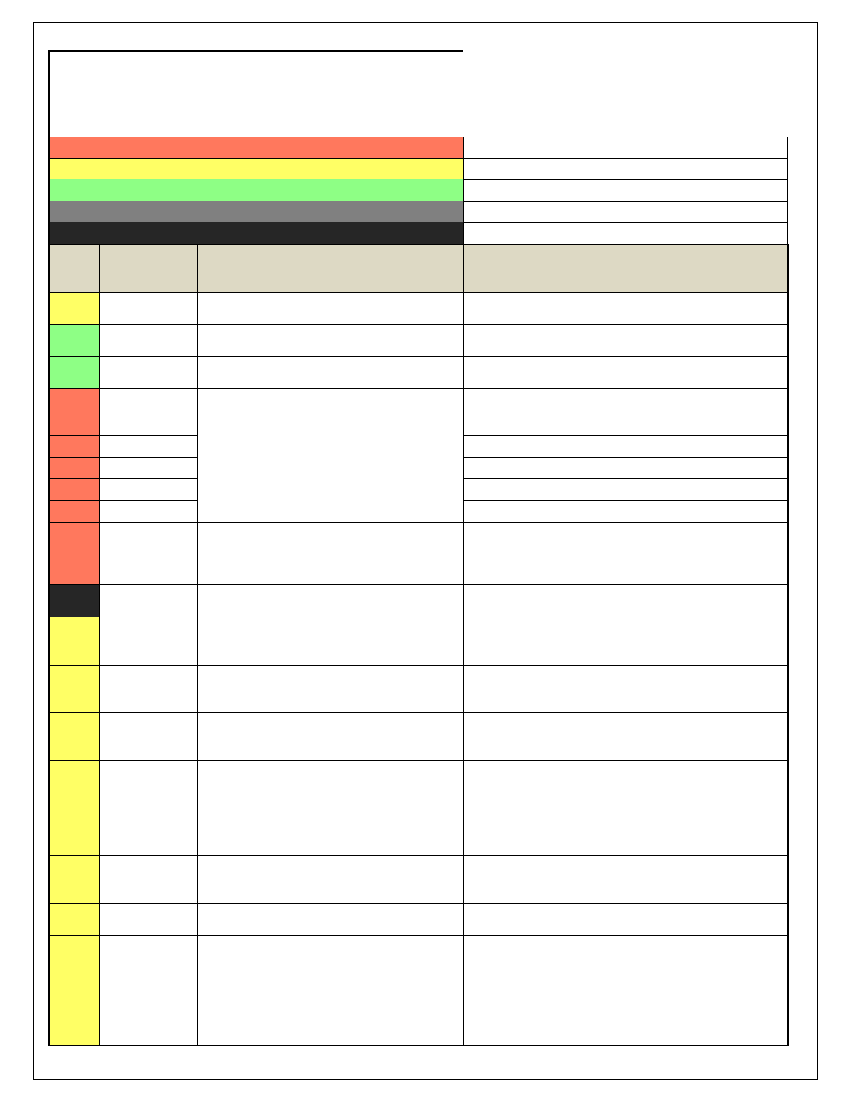
Dedicated
Dedicated and not reconfigurable
Assigned
Assigned but reconfigurable
Available
Available for user setup
Not Applicable
Not used in this configuration
Required
Required for proper function
Infinity
Pin
Hrdwr Ref.
Hardware Specification
Notes
C1-1
LowsideSwitch_4
Lowside switch, 4A max, NO internal flyback diode.
See Setup Wizard Pages "User GPOs" for activation criteria and
"LowSide Assignment Tables" for output assignment
C1-2
LowsideSwitch_5
Lowside switch, 4A max with internal flyback diode.
Inductive load should NOT have full time power.
See Setup Wizard Page "LowSide Assignment Tables" for output
assignment and 2D table "LS5_Duty [%]" for activation.
C1-3
LowsideSwitch_6
Lowside switch, 4A max with internal flyback diode.
Inductive load should NOT have full time power.
See Setup Wizard Page "LowSide Assignment Tables" for output
assignment and 2D table "LS6_Duty [%]" for activation.
C1-4
UEGO 1 Heat
Bosch UEGO controller
Lowside switch for UEGO heater control. Connect to pin 4 of
Bosch UEGO sensor. NOTE that pin 3 of the Sensor is heater (+)
and must be power by a fused/switched 12V supply.
C1-5
UEGO 1 IA
Trim Current signal. Connect to pin 2 of Bosch UEGO sensor
C1-6
UEGO 1 IP
Pumping Current signal. Connect to pin 6 of Bosch UEGO sensor
C1-7
UEGO 1 UN
Nernst Voltage signal. Connect to pin 1 of Bosch UEGO sensor
C1-8
UEGO 1 VM
Virtual Ground signal. Connect to pin 5 of Bosch UEGO sensor.
C1-9
Flash_Enable
10K pulldown
Not usually needed for automatic firmware updates through
Infinity Tuner. If connection errors occur during update,
connect 12 volts to this pin before proceeding with upgrade.
Disconnect the 12 volts signal after the update.
C1-10
+12V_R8C_CPU
Dedicated power management CPU
Full time battery power. MUST be powered before the ignition
switch input is triggered (See C1-65).
C1-11
Coil 4
25 mA max source current
0-5V Falling edge fire. DO NOT connect directly to coil primary.
Must use an ignitor OR CDI that accepts a FALLING edge fire
signal.
C1-12
Coil 3
25 mA max source current
0-5V Falling edge fire. DO NOT connect directly to coil primary.
Must use an ignitor OR CDI that accepts a FALLING edge fire
signal.
C1-13
Coil 2
25 mA max source current
0-5V Falling edge fire. DO NOT connect directly to coil primary.
Must use an ignitor OR CDI that accepts a FALLING edge fire
signal.
C1-14
Coil 1
25 mA max source current
0-5V Falling edge fire. DO NOT connect directly to coil primary.
Must use an ignitor OR CDI that accepts a FALLING edge fire
signal.
C1-15
Coil 6
25 mA max source current
0-5V Falling edge fire. DO NOT connect directly to coil primary.
Must use an ignitor OR CDI that accepts a FALLING edge fire
signal.
C1-16
Coil 5
25 mA max source current
0-5V Falling edge fire. DO NOT connect directly to coil primary.
Must use an ignitor OR CDI that accepts a FALLING edge fire
signal.
C1-17
LowsideSwitch_2
Lowside switch, 4A max, NO internal flyback diode.
See Setup Wizard Pages "User GPOs" for activation criteria and
"LowSide Assignment Tables" for output assignment
C1-18
LowsideSwitch_3
Lowside switch, 4A max with internal flyback diode.
Inductive load should NOT have full time power.
See Wizard page "LowSide Assignment Tables" for output
assignment.
MIL Activates when any of the following flags are true:
ErrorAirTemp, ErrorBaro, ErrorCoolantTemp, ErrorEBP,
ErrorFuelPressure, UEGO_0_Diag_error, UEGO_1_Diag_error,
ErrorMAFAnalog, ErrorMAFDigital, ErrorMAP, ErrorOilPressure,
ErrorThrottle.