AEM 30-3532 GM LS 24x Engines Layover User Manual
Page 19
Rev A, 2013/02/05
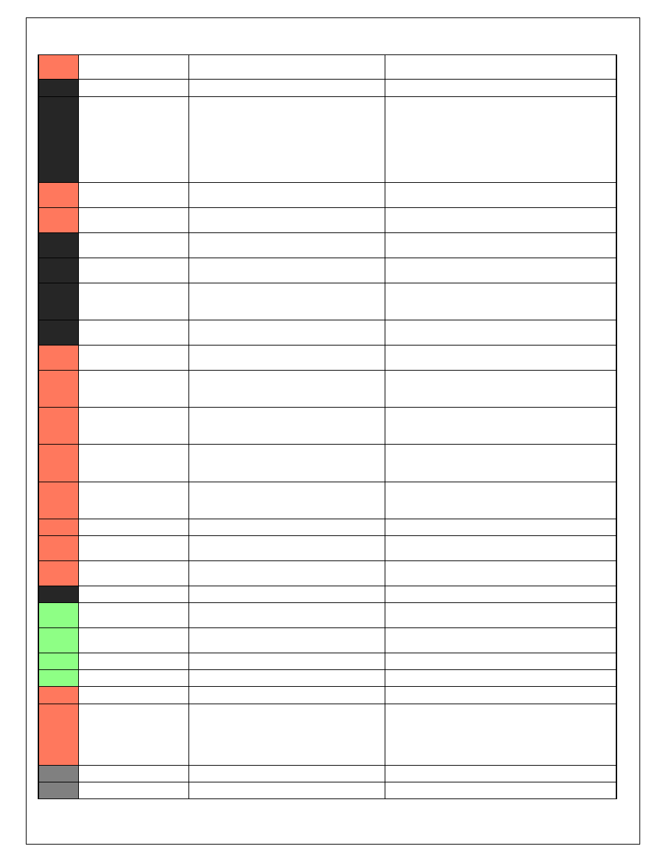
C1-59
Injector 3
Saturated or peak and hold, 3A max continuous
Injector 3
C1-60
Power Ground
Power Ground
Connect directly to battery ground
C1-61
+12V
12 volt power from relay
12 volt power from relay. Relay must be controlled by
+12V Relay Control signal, pin C1-29 above.
C1-62
Injector 2
Saturated or peak and hold, 3A max continuous
Injector 2
C1-63
Injector 1
Saturated or peak and hold, 3A max continuous
Injector 1
C1-64
+12V
12 volt power from relay
12 volt power from relay. Relay must be controlled by
+12V Relay Control signal pin C1-29 above.
C1-65
+12V_SW
10K pulldown
Full time battery power must be available at C1-10 before
this input is triggered.
C1-66
Analog_In_Temp_1
12 bit A/D, 2.49K pullup to 5V
See "Coolant Temperature" Setup Wizard for selection.
C1-67
Analog_In_Temp_2
12 bit A/D, 2.49K pullup to 5V
See "Air Temperature" Setup Wizard for selection.
C1-68
Harness_Analog_In_Temp
_3
12 bit A/D, 2.49K pullup to 5V
See 1D table OilTempCal table for calibration data and
OilTemp [C] for channel data.
C1-69
Stepper_2A
Automotive, Programmable Stepper Driver, up
to 28V and ±1.4A
Be sure that each internal coil of the stepper motor are
properly paired with the 1A/1B and 2A/2B ECU outputs.
Supports Bi-Polar stepper motors only.
C1-70
Stepper_1A
Automotive, Programmable Stepper Driver, up
to 28V and ±1.4A
Be sure that each internal coil of the stepper motor are
properly paired with the 1A/1B and 2A/2B ECU outputs.
Supports Bi-Polar stepper motors only.
C1-71
Stepper_2B
Automotive, Programmable Stepper Driver, up
to 28V and ±1.4A
Be sure that each internal coil of the stepper motor are
properly paired with the 1A/1B and 2A/2B ECU outputs.
Supports Bi-Polar stepper motors only.
C1-72
Stepper_1B
Automotive, Programmable Stepper Driver, up
to 28V and ±1.4A
Be sure that each internal coil of the stepper motor are
properly paired with the 1A/1B and 2A/2B ECU outputs.
Supports Bi-Polar stepper motors only.
C1-73
Power Ground
Power Ground
Connect directly to battery ground
C2-1
DBW2 Motor +
5.0A max Throttle Control Hbridge Drive
+12V to open
C2-2
DBW2 Motor -
5.0A max Throttle Control Hbridge Drive
+12V to close
C2-3
Power Ground
Power Ground
Connect directly to battery ground
C2-4
Injector 7
Saturated or peak and hold, 3A max continuous
Injector 7
C2-5
Injector 8
Saturated or peak and hold, 3A max continuous
Injector 8
C2-6
Injector 9
Saturated or peak and hold, 3A max continuous
Injector 9
C2-7
Injector 10
Saturated or peak and hold, 3A max continuous
Injector 10
C2-8
Power Ground
Power Ground
Connect directly to battery ground
C2-9
+12V
12 volt power from relay
12 volt power from relay. Relay must be controlled by
+12V Relay Control signal, pin C1-29 above.
C2-10
Injector 11
Saturated or peak and hold, 3A max continuous
Not used
C2-11
Injector 12
Saturated or peak and hold, 3A max continuous
Not used