AEM 30-3532 GM LS 24x Engines Layover User Manual
Page 17
Rev A, 2013/02/05
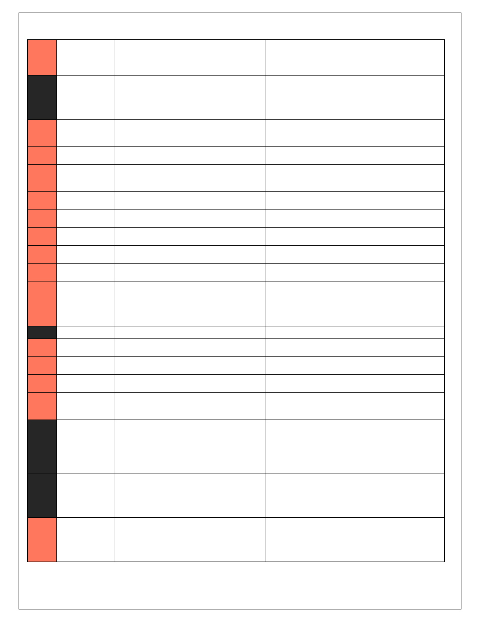
C1-19
AGND_1
Dedicated analog ground
Analog 0-5V sensor ground
C1-20
AGND_1
Dedicated analog ground
Analog 0-5V sensor ground
C1-21
Crankshaft
Position Sensor
Hall
10K pullup to 12V. Will work with ground or
floating switches.
See Setup Wizard page Cam/Crank for options.
C1-22
Camshaft Position
Sensor 1 Hall
10K pullup to 12V. Will work with ground or
floating switches.
See Setup Wizard page Cam/Crank for options.
C1-23
Digital_In_2
10K pullup to 12V. Will work with ground or
floating switches.
See Setup Wizard page Cam/Crank for options.
C1-24
Digital_In_3
10K pullup to 12V. Will work with ground or
floating switches.
See Setup Wizard page Turbo Speed for calibration constant.
TurboSpeed [RPM] = Turbo [Hz] * Turbo Speed Calibration.
C1-25
Digital_In_4
10K pullup to 12V. Will work with ground or
floating switches.
See Setup Wizard page Vehicle Speed for calibration constant.
C1-26
Digital_In_5
10K pullup to 12V. Will work with ground or
floating switches.
See channel FlexDigitalIn [Hz] for raw frequency input data.
C1-27
Knock Sensor 1
Dedicated knock signal processor
See Setup Wizard page Knock Setup for options.
C1-28
Knock Sensor 2
Dedicated knock signal processor
See Setup Wizard page Knock Setup for options.
C1-29
+12V_Relay_Cont
rol
0.7A max ground sink for external relay control
Will activate at key on and at key off according to the
configuration settings.
C1-30
Power Ground
Power Ground
Connect directly to battery ground
C1-31
CANL_Aout
Dedicated High Speed CAN Transceiver
Recommend twisted pair (one twist per 2") with terminating
resistor. Contact AEM for additional information.
C1-32
CANH_Aout
Dedicated High Speed CAN Transceiver
Recommend twisted pair (one twist per 2") with terminating
resistor. Contact AEM for additional information.
C1-33
LowsideSwitch_1
Lowside switch, 4A max with internal flyback diode.
Inductive load should NOT have full time power.
See Setup Wizard page Boost Control for options. Monitor
BoostControl [%] channel for output state.
C1-34
Lowside Fuel
Pump drive
Lowside switch, 4A max, NO internal flyback diode.
Switched ground. Will prime for 2 seconds at key on and
activate if RPM > 0.
C1-35
Analog_In_7
12 bit A/D, 100K pullup to 5V
0-5V analog signal. Use +5V Out pins as power supply and
Sensor Ground pins as the low reference. Do not connect
signals referenced to +12V as this can permanently damage
the ECU. See the Setup Wizard Set Throttle Range page for
automatic min/max calibration. Monitor the Throttle [%]
channel. Also DB1_TPSA [%] for DBW applications.
C1-36
Analog_In_8
12 bit A/D, 100K pullup to 5V
0-5V analog signal. Use +5V Out pins as power supply and
Sensor Ground pins as the low reference. Do not connect
signals referenced to +12V as this can permanently damage
the ECU. See the Setup Wizard Set Manifold Pressure page for
setup and calibration. Monitor the MAP [kPa] channel.
C1-37
Analog_In_9
12 bit A/D, 100K pullup to 5V
0-5V analog signal. Use +5V Out pins as power supply and
Sensor Ground pins as the low reference. Do not connect
signals referenced to +12V as this can permanently damage
the ECU. See the Setup Wizard Fuel Pressure page for setup
and calibration. Monitor the FuelPressure [psig] channel.