AEM 30-2340 4-Channel Wideband UEGO AFR Controller User Manual
Page 8
Page 8 10-2340 Rev 05 121012
NOTE: THE SERIES 2 EMS DOES NOT USE INFORMATION TRANSMITTED ON
AEMnet FOR 02 FEEDBACK. THE SERIES 2 EMS USES THE ANALOG INPUTS
FOR 02 FEEDBACK. SEE THE SECTION ON ANALOG INPUTS FOR INFORMATION
ON CONNECTING THE ANALOG INPUTS.
NON-AEM PRODUCTS
Each AEMnet connector has 4 pins. The AEMnet pinout is listed below in Table 2.
NOTE: Pin numbers are located at the back of the connector. Non-AEM devices can
connect to the AEMnet by connecting their CAN +/- wires to the CAN+/- wires on the
AEM network. The connectors are shown in Figure 7.
AEMnet Connector
Pin 1
White
CAN +
Pin 2
Green
CAN -
Pin 3
Red
12 Volts
Pin 4
Black
Ground
Table 2. AEMnet Pinout
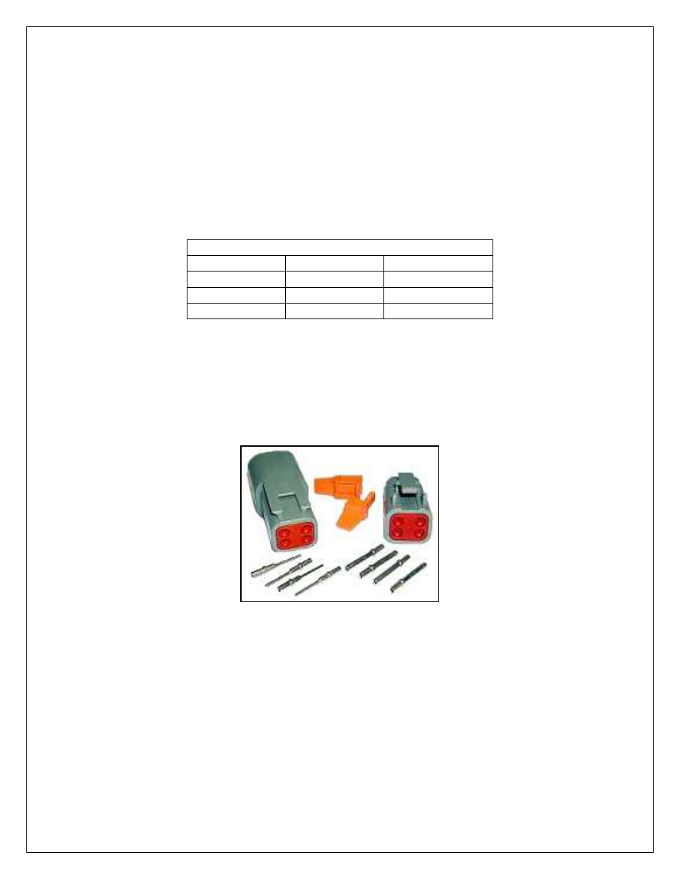
•
Deutsch DTM04-4P (Receptacle connector)
•
Deutsch 1060-20-0222 (Pins)
•
Deutsch DTM06-4S (Plug connector)
•
Deutsch 1062-20-0222 (Pins)
Figure 7. Connector Assembly
NOTE: the 4 CH UEGO controller has one terminating resistor. If an additional
terminating resistor is needed, one must be installed on the other device.
- 30-71XX Infinity EMS Quick Start Guide (53 pages)
- 23-800BK Tru-Time Adjustable Cam Gear (7 pages)
- 23-801BK Tru-Time Adjustable Cam Gear (11 pages)
- 23-830BK Tru-Time Adjustable Cam Gear (8 pages)
- 23-831BK Tru-Time Adjustable Cam Gear (7 pages)
- 23-850BK Tru-Time Adjustable Cam Gear (6 pages)
- 23-851BK Tru-Time Adjustable Cam Gear (7 pages)
- 25-100BK High Volume Fuel Rail (5 pages)
- 25-104BK High Volume Fuel Rail (5 pages)
- 25-108BK High Volume Fuel Rail (7 pages)
- 25-109BK High Volume Fuel Rail (6 pages)
- 25-111BK High Volume Fuel Rail (6 pages)
- 25-130BK High Volume Fuel Rail (6 pages)
- 25-131BK High Volume Fuel Rail (4 pages)
- 25-200BK Honda/Acura High Volume Fuel Filter (3 pages)
- 25-201BK Universal High Volume Fuel Filter (4 pages)
- 25-300BK Honda/Acura Adjustable Fuel Pressure Regualtor (9 pages)
- 25-302BK Universal Adjustable Fuel Pressure Regualtor (5 pages)
- 25-391 High Volume Fuel Rail AN Adapter Kit (5 pages)
- 25-392 Honda/Acura Adjustable Fuel Pressure Regualtor (4 pages)
- 30-1910 Universal Fuel Ignition Controller 6 Channel (33 pages)
- 30-1930 Universal Fuel Ignition Controller 8 Channel (34 pages)
- 30-1960 Plug & Play Fuel Ignition Controller 6 Channel (5 pages)
- 30-2010 Air Temp Sensor Kit (2 pages)
- 30-2011 Water Temp Sensor Kit (2 pages)
- 30-2012 Water Temp Sensor Kit (2 pages)
- 30-2020 Bosch Injector Plug Kit 4 Pack (2 pages)
- 30-2050 RTD Temperature Sensor Kit (1 page)
- 30-2056 Universal 12 Position Trim Pot (1 page)
- 30-2065 K-Type Closed Tip Thermocouple Sensor Kit (2 pages)
- 30-2066 K-Type Closed Tip Thermocouple 10 Wiring Extension Kit (2 pages)
- 30-2067 X-WiFi K-Type Closed Tip Thermocouple Kit (2 pages)
- 30-2130-XXX Stainless Steel Pressure Sensor (2 pages)
- 30-2131-XXX Brass Pressure Sensor (2 pages)
- 30-2204 K-Type Thermocouple Amplifier 4 Channel (6 pages)
- 30-2310 Inline Wideband UEGO Controller (8 pages)
- 30-2067 X-WiFi Wideband UEGO & EGT Controller (14 pages)
- 30-2340-N 4-Channel Wideband UEGO AFR Controller - For use with Nascar McLaren ECU (28 pages)
- 30-2355-XXX No-Weld O2 Sensor Mount (4 pages)
- 30-2400 Boost Control Solenoid Kit (2 pages)
- 30-2500 AQ-1 Data Logging System (22 pages)
- 30-2710 Peak & Hold Injector Driver 10 Channel (5 pages)
- 30-2840 4 Channel Coil Driver (2 pages)
- 30-2841 1 Channel Coil Driver (4 pages)