AEM 30-2340 4-Channel Wideband UEGO AFR Controller User Manual
Page 12
Page 12 10-2340 Rev 05 121012
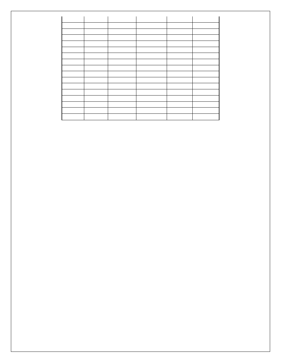
1.34
0.71
10.5
4.6
6.9
6.4
1.55
0.75
11.0
4.8
7.3
6.7
1.76
0.78
11.5
5.0
7.6
7.0
1.97
0.82
12.0
5.2
7.9
7.3
2.18
0.85
12.5
5.4
8.2
7.7
2.39
0.88
13.0
5.7
8.6
8.0
2.61
0.92
13.5
5.9
8.9
8.3
2.82
0.95
14.0
6.1
9.2
8.6
3.03
0.99
14.5
6.3
9.6
8.9
3.11
1.00
14.7
6.4
9.7
9.0
3.24
1.02
15.0
6.5
9.9
9.2
3.45
1.05
15.5
6.7
10.2
9.5
3.66
1.09
16.0
7.0
10.6
9.8
3.87
1.12
16.5
7.2
10.9
10.1
4.08
1.16
17.0
7.4
11.2
10.4
4.29
1.19
17.5
7.6
11.5
10.7
4.50
1.22
18.0
7.8
11.9
11.0
Outputs
The harness for the 4 Channel UEGO controller contains a bundle of 5 output wires.
The four white wires are labeled AFR 1, AFR 2, AFR 3, and AFR 4. The black wire is
labeled SIG GND. Connect the wires as listed below.
WHITE – Connect to Lambda + Input.
BLACK – Connect to sensor ground. Connect to power ground if sensor ground is not
available.
EMS Setup
Connect two WHITE AFR output + wires to O2 #1 and O2 #2 EMS analog input pins.
Connect the BLACK Analog Output – wire to the EMS sensor ground.
NOTE: The current version of EMS has only two input pins dedicated to O2 analog
inputs. To view the analog outputs from all four channels use spare analog inputs, i.e.,
EGT1 ~ 4.
Tuner Setup (Must use 01v22 firmware or newer)
With an EMS calibration open in the AEMTuner software, go to Wizards -> Setup
Wizard and choose Sensor: 02 #1 (AFR) and Sensor 02 #2 (AFR). Under Configuration
Name, choose AEM (4-Channel UEGO PN 30-2340) and click Apply. When the
configuration is set, as shown in figure 10, close the wizard.
TABLE 3. AFR Values