Analog output – AEM 30-2340 4-Channel Wideband UEGO AFR Controller User Manual
Page 11
Page 11 10-2340 Rev 05 121012
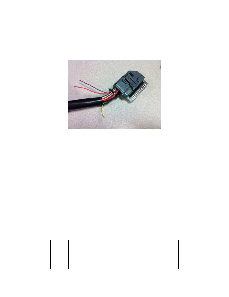
show the selected mode. The number of Status/Error LED’s illuminated corresponds to
the mode selected. When a desired mode is selected, disconnect both CONFIG wires
from the GROUND wire. The mode will be saved in the controller and the LEDs of the
corresponding mode will blink three times. When more than one 4 CH UEGO
controller is connected to the net, the controllers must be in different modes.
Make sure that each controller is set into the correct mode. Upon powering up, the
number of LEDs corresponding to the mode will blink three times to indicate the mode.
For example, if in mode 7, 7 LED’s will blink 3 times.
FIGURE 9. Mode Configuration Wires
ANALOG OUTPUT
The analog output from the 4 CH UEGO controller is a linear dc voltage signal that
varies from 0.5 Vdc at 8.5:1 AFR Gasoline (0.58 Lambda) to 4.5Vdc at 18.0:1 AFR
Gasoline (1.22 Lambda). The signal is used for sending information to a data logger or
an engine management system such as the AEM EMS or F/IC. The transfer function
for the output is listed below.
AFR Gasoline = 2.375(V) + 7.3125
For example, if the output is 2.0 Vdc, the AFR is 12.06:1
2.375 * 2.0 + 7.3125 = 12.06
A table showing the analog output voltage and corresponding Air/Fuel ratios for some of
the common fuels is shown below in Table 3
.
VOLTS
LAMBDA
AFR GAS
AFR
METHANOL
AFR E85
AFR
ETHANOL
0.50
0.58
8.5
3.7
5.6
5.2
0.71
0.61
9.0
3.9
5.9
5.5
0.92
0.65
9.5
4.1
6.3
5.8
1.13
0.68
10.0
4.4
6.6
6.1