Warning – Burnham V9A User Manual
Page 17
17
WARNING
When tightening the draw-up nuts, DO NOT
EXCEED 150 FT-LB OF TORQUE. If the maximum
torque limit has been reached and a gap greater
than .025” still exists between the sections,
consult the regional office.
KEEP NIPPLES ALIGNED WITH NIPPLE
PORTS. If necessary, tap edge of nipples lightly
with a blunt tool or rod to keep nipples from
cocking while sections are being drawn-up. DO
NOT DRAW UP SECTION WHEN NIPPLES
ARE COCKED. If the torque required becomes
excessive, periodically place a heavy block of
wood over each nipple port and strike as squarely
as possible with several blows to relieve tension
on the draw-up rods.
n. CONTINUE ASSEMBLING SECTIONS IN
THEIR RESPECTIVE ORDER alternating
draw-up rods from the upper to lower set of
holes in draw-up lugs (see Figure 13). Be certain
that all sections are drawn up iron-to-iron at all
three (3) nipple ports.
BE SURE TO APPLY THE SEALANT to
the groove in the ground joints between
adjacent sections as the boiler operates with a
positive pressure in the firebox and products of
combustion will escape between sections unless
the sections are properly sealed. The sealant
should be applied before each section is placed
on the assembly.
o. If a joint springs apart it must be redrawn tight
within four (4) hours of the time of application of
Silastic to that joint.
p. EXCESS LENGTH OF DRAW-UP RODS must
not extend beyond front and rear section to
ensure proper fit of jacket, adjust accordingly.
q. After all sections have been drawn up, the
draw-up rod nuts should be loosened until
finger tight and then tightened ½ turn with a
wrench.
r. Now Proceed to Paragraph C of this Section,
Hydrostatic Test.
2. ASSEMBLY OF SECTIONS (HYDRAULIC
DRAW-UP)
The entire boiler assembly may be drawn up at one
time using hydraulic draw-up equipment providing
the operation is completed within two (2) hours after
application of the sealant.
a. Repeat steps 1a through 1k under “Field
Assembled Sections (Manual Draw-Up).”
b. Continue driving sections in place (in their
respective order) until all sections are in the
assembly. Ground surfaces between adjoining
sections should be spaced 1/4” to 3/8” apart.
Spacing of more than 3/8” will limit number of
sections that can be drawn up in one unit and
could indicate cocked nipples.
WARNING
Sealant must be properly applied to ALL boiler
joints. Failure to properly seal the boiler joints
will result in combustion gas leaks through to
joint. DO NOT operate boiler with combustion
gas leaks. The sealant should be applied before
each section is placed on the assembly.
On long boiler assemblies, it may be necessary to
draw-up a partial block if the entire boiler is not
ready to be drawn-up tight within two (2) hours
of the first application of Silastic. If the block
assembly time extends overnight, the partial
block completed must be drawn-up tight before
leaving the boiler overnight. If a joint springs
out, it must be redrawn tight within four (4)
hours of first application of Silastic to the joint.
c. Insert the three (3) ¾” draw-up rods (and
couplings, if appropriate) through the tapped
holes in the rear section extending them through
the tapped holes in the front section. Be sure to
screw draw-up rods into couplings far enough to
prevent stripping threads.
d. Place a 3” x 12” lg. steel channel on each end of
the upper draw-up rod and a 3” x 8½” lg. steel
channel on each end of the lower draw-up rods.
Refer to Figures 10 and 11 for proper placement
of channel block during assembly procedures.
Install nuts and washers on one end of the draw-
up rods and the hydraulic rams, washers and
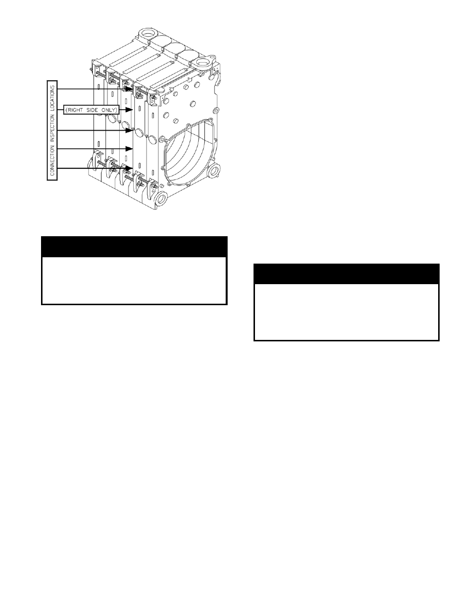
Figure 9: Connection Inspection Locations and
Manual Draw-Up Tie Rod Pattern