Caution – Burnham V9A User Manual
Page 16
16
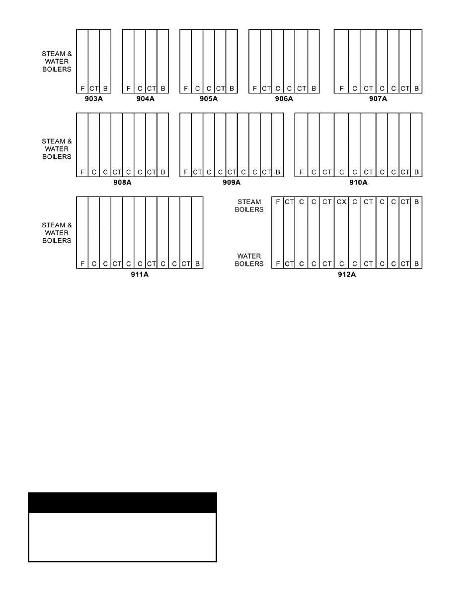
Figure 8: V9A Section Arrangement
j. Clean and lubricate nipple ports on next section
to be assembled and place on nipples previously
installed in rear section. To facilitate assembly,
it is advisable to enter the upper nipple first in
its port. Then enter the lower nipples in their
respective ports. If necessary, place a lifting bar
(crowbar) under the center of the section and lift
the nipple port onto the upper nipple.
k. Drive sections in place with a heavy block of
wood, striking blows as squarely as possible over
nipple port.
l. The large draw-up rod lugs with dual holes
are cast in the four (4) corners of each casting.
STARTING WITH THE UPPER HOLES,
install four (4) 5/8” x 9¾” long draw-up rods
along with washers and nuts (see Figure 9).
CAUTION
To avoid damage to the draw-up rod threads while
drawing up sections, apply oil or other lubricant
to tie rod threads while assembling sections to
prevent stripping of threads on rod and to make
assembling easier.
m. DRAW UP SECTION SLOWLY AND
EVENLY using an alternating pattern starting
with the upper right lug (closest to the 7” port)
and proceeding to the lower left , lower right
and finishing with upper left lug. When you
start, grind surfaces between adjoining sections
should be approximately 3/8” apart. Use
three (3) or four (4) passes at tightening the
four (4) draw-up rods a little at a time so that
sections are pulled up evenly. During the last
pass, pay close attention to the silastic sealant
as it squeezes when the sections come in close
contact. The silastic sealant should continue
to squeeze out wafer thin until the sections are
connected metal to metal. If the silastic has
stopped squeezing out from the connection and
the sections still do not appear to be drawn metal
to metal, use a feeler gauge to measure any gaps
at the locations identified in Figure 9. (Unless
specified otherwise, gaps should be measured at
these locations on both sides of the sections.) A
maximum gap of .025” is acceptable. Measure
gaps at the outer edge of the connection only,
making sure not to puncture the gasket created
by the silastic and rope.
NOTES: FOR BOILERS LESS TANKLESS HEATER, REPLACE THE "CT" SECTIONS WITH "C" SECTIONS.
TANKLESS SECTIONS: IF BOILER CAN TAKE MULTIPLE TANKLESS COILS, BUT NOT ALL
TANKLESS COILS WILL BE USED, INSTALL COILS TOWARDS BACK OF BOILER, FOLLOWING
SECTION ARRANGEMENT CHART.