Bosch 8-Dec User Manual
Page 69
Control Panels, Control Centers, and Keypads | UEZ 2000 | 61
SRT system parameters
Signaling devices
32 per system, max. 99 in the cluster
Transmission equipment
48 in the cluster
Auto dialer
1 per system
Printer
1 per system
Timer channels
9 per system
BE 1000 operating unit
4 per system
Priority control panel
2 per system
Alarm counter
2 per system
Event database
1 per system
Internal programs
14 in cluster
User ID
Up to 255 in cluster
Monitoring texts
Up to 20 in cluster
Alarm texts
Up to 40 in cluster
System short texts
Up to 300 in cluster
Detector short texts (location) 2032 in cluster
Hold-up camera
6 per system
Partitions
32 in cluster
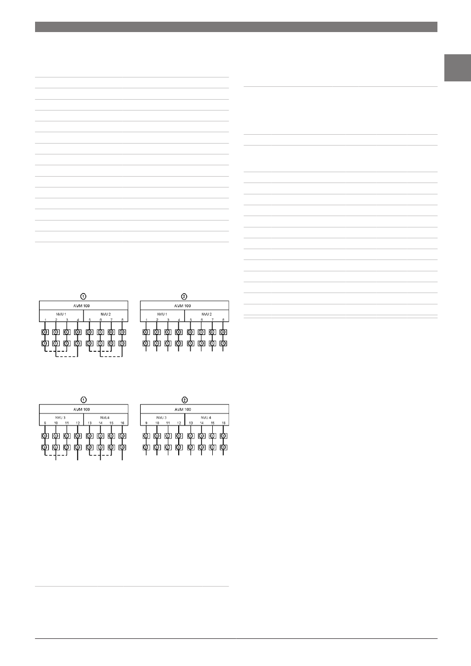
Creating loop and stub lines
Basic version with 1 x LVM 100
(4 loops or 8 stubs or any preferred combination of the two)
Extension with second LVM 100 (only with UEZ 2000 LSN)
(Additional 4 loops or 8 stubs or any preferred combination
of the two)
1
Loop connection
2
Stub connection
3
LSN elements
NVU parameters: 2 loops or 4 stubs, up to 1000 m in cable
length, up to 100 mA current consumption, up to 127 LSN
elements
Quantity structure for the SRT system cluster with UEZ
2000 LSN
Maximum number of detectors
Number of
systems
1
2
3
4
5
6
508
1016
1524
2032
2032
2032
Maximum number of detector zones
Number of
systems
1
2
3
4
5
6
127
256
381
508
508
508
Module quantity structure in UEZ 2000 LSN emergency
call SRT
Quantity structure
Loops
Optocou-
pler
Fiber op-
tics or mo-
dem
UEZ 2000
LVM 100
SEMO
SM20*
SM24*
4
1
8
1
1
12
2
1
2
4
4
16
2
2
2
4
4
20
3
2
3
6
6
24
3
3
3
6
6
28
4
3
4
8
8
32
4
4
4
8
8
36
5
4
5
10
10
40
5
5
5
10
10
44
6
5
6
12
12
48
6
6
6
12
12
* Either a modem or a fiber optics converter is required in addition
to the SM 24
Note
The limit values for each NVU or LVM 100 must
be observed.
Note
For mixed configurations, the number of SM20
and SM24 modules required changes
(increases or decreases).
www.boschsecurity.com
Bosch Security Systems B.V.
1