Connecting up 02, Easy connections, Using other types of audio/video output – Pioneer RCS-656HX User Manual
Page 48: Coaxial, Output input3 in, Using the s-video or component video output
Connecting up
02
48
En
Easy connections
The setup described below is a basic setup that allows
you to watch and record TV programs, and play discs.
Other types of connections are explained starting on the
following page.
Important
• These connections use SCART cables (not supplied). If
your TV (or VCR) does not have a SCART connection, if
you want to use the supplied audio/video cable, see
Using the S-video or component video output on
page 48.
• The
AV1(RGB)-TV AV connector can output ordinary
(composite), S-video or RGB video, plus stereo analog
audio. The
AV2(INPUT 1/DECODER) connector
accepts ordinary, S-video and RGB video input, as well
as stereo analog audio. See AV1 Out on page 132 and
AV2/L1 In on page 132 for how to set them up.
• Before making or changing any rear panel
connections, make sure that all components are
switched off and unplugged from the wall outlet.
1
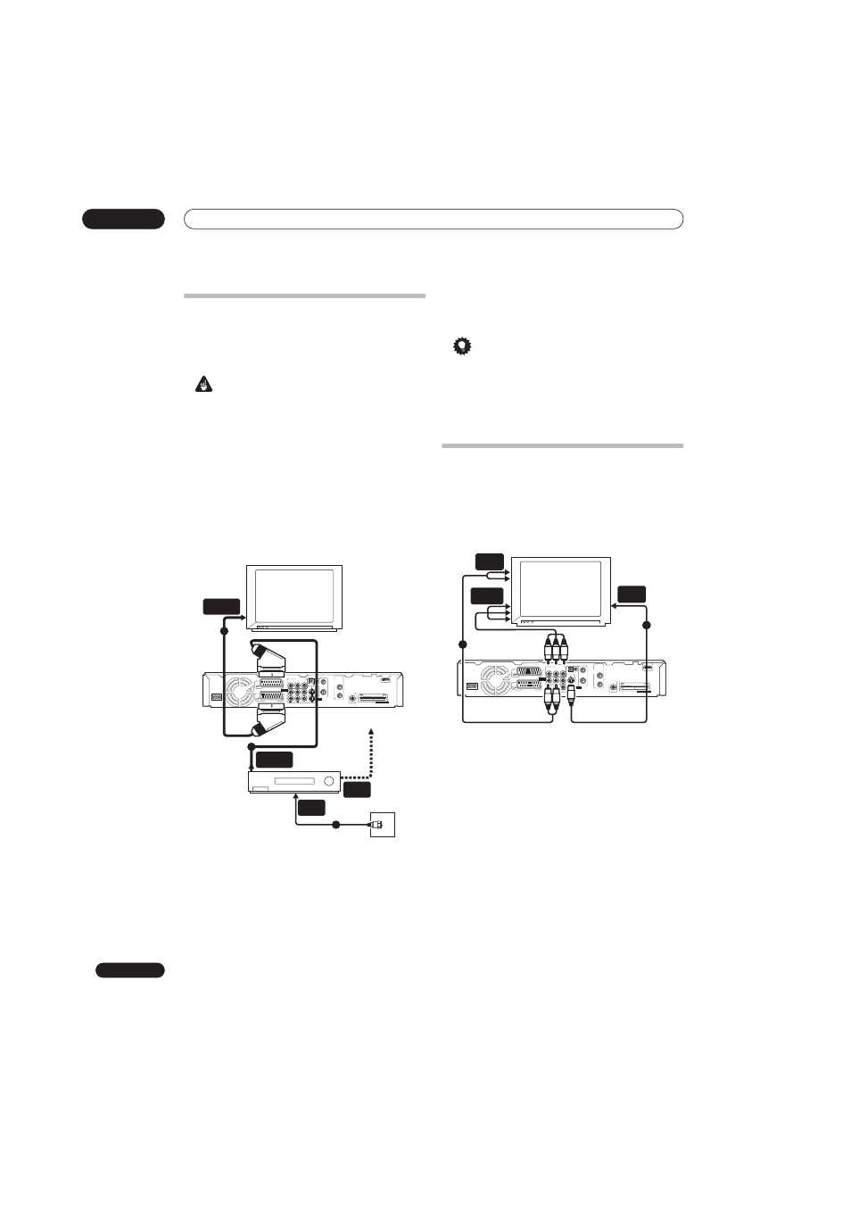
Connect your TV antenna to the recorder and TV.
See Connecting a TV antenna on page 47 for details.
• If you want to incorporate a VCR in your setup, connect
it before the recorder (i.e., between the antenna wall
outlet and the antenna input on the recorder).
2
Use a SCART cable (not supplied) to connect the
AV1(RGB)-TV
AV connector on this recorder to the
SCART AV connector on your TV.
3
Use another SCART cable to connect the AV2(INPUT
1/DECODER)
AV connector to a SCART AV connector on
your VCR.
Tip
• This recorder has a ‘through’ function which allows
you to record a TV program from the built-in TV tuner
in this recorder while watching a video playing on
your VCR (To use this feature when the recorder is in
standby,
Power Save must be set to Off—see Power
Save on page 129).
Using other types of audio/video
output
If you can’t use the SCART AV connector to connect your
TV to this recorder, there are standard audio/video output
jacks, as well as an S-video and component video output.
Using the S-video or component video output
1
Connect the S-video or component video output
to a similar input on your TV.
For an S-video connection, use an S-video cable (not
supplied) to connect the
S-VIDEO OUTPUT jack to an S-
video input on your TV.
For a component video connection, use a component
video cable (not supplied) to connect the
COMPONENT
VIDEO OUT jacks to a component video input on your TV.
See also Component Video Out on page 132 for how to set
up the component video output for use with a progressive
scan-compatible TV.
2
Connect the AUDIO OUTPUT jacks to the
corresponding audio inputs on your TV.
You can use the supplied audio/video cable, leaving the
yellow video plug disconnected. Make sure you match up
the left and right outputs with their corresponding inputs
for correct stereo sound.
TV
To recorder's
antenna input
VCR
Antenna/cable TV
wall outlet
HDMI OUT
ANTENNA
IN
OUT
DIGITAL
AUDIO OUT
COAXIAL
ANTENNA
(DIGITAL)
IN
OUT
VIDEO
L
R
COMPONENT
VIDEO OUT
S-VIDEO
OUTPUT
INPUT3
IN
CONTROL G-LINK
AV 1 (RGB) – TV
AV 2 (INPUT 1/DECODER)
AC IN
COMMON INTERFACE
AUDIO
P
B
Y
SCART AV
CONNECTOR
SCART AV
CONNECTOR
ANTENNA
OUT
ANTENNA
IN
1
2
2
3
TV
HDMI OUT
ANTENNA
IN
OUT
DIGITAL
AUDIO OUT
COAXIAL
ANTENNA
(DIGITAL)
IN
OUT
VIDEO
L
R
COMPONENT
VIDEO OUT
S-VIDEO
OUTPUT
INPUT3
IN
CONTROL G-LINK
AV 1 (RGB) – TV
AV 2 (INPUT 1/DECODER)
AC IN
COMMON INTERFACE
AUDIO
P
B
P
R
Y
S-VIDEO
INPUT
COMPONENT
VIDEO INPUT
AUDIO
INPUT
1
2