Seiwa Si-Tex Vector 3D GPS User Manual
Page 9
10
8
Vector 3D User Guide
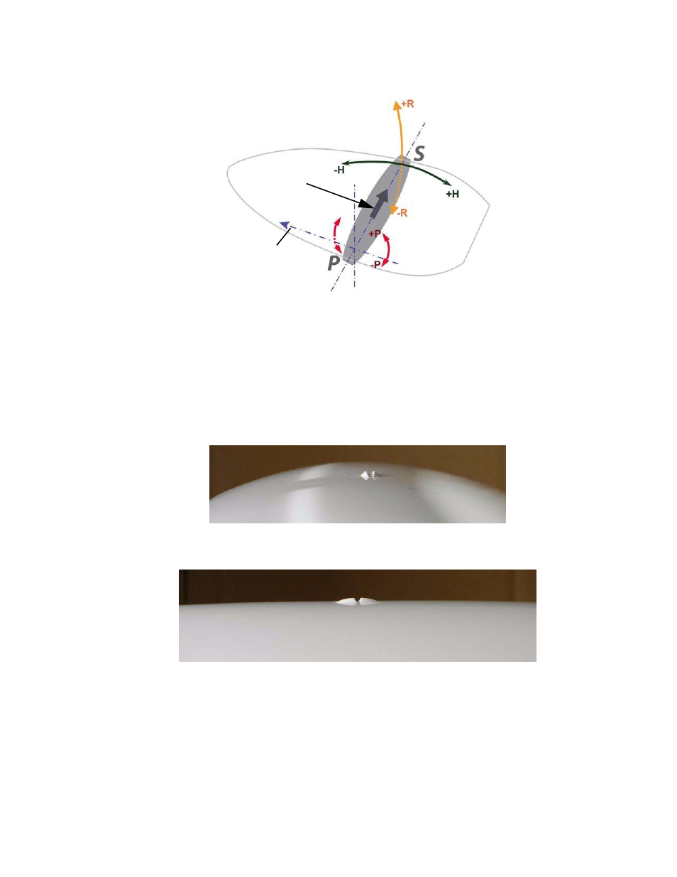
Recessed arrow
located on
bottom of
enclosure
Forward
motion
Figure 2-3: Alternate orientation and resulting signs of HPR values
3D Alignment
The top of the 3D enclosure incorporates sight design features to help you align the enclosure with respect to
an important feature on your vessel.
To use the sights, center the small post on the opposite side of the enclosure from you, within the channel
made in the medallion located in the center of the enclosure top as shown in Figure 2-4 and Figure 2-5.
Alignment accuracy when looking through the long site (Figure 2-4) is approximately +/- 1°, while
alignment through the short site (Figure 2-5) is approximately +/- 2.5°
.
Figure 2-4: Long site alignment
Figure 2-5: Short sight alignment
If you have another accurate source of heading data on your vessel, such as a gyrocompass, you may use its
data to correct for a bias in 3D alignment within the 3D software configuration. Alternatively, you can
physically adjust the heading of the 3D so that it renders the correct heading measurement; however, adding
a software offset is an easier process
.