Vector 3d overview – Seiwa Si-Tex Vector 3D GPS User Manual
Page 23
26
23
Chapter 3: Operation
Vector 3D Overview
The 3D provides accurate and reliable heading and position information at high update rates. To accomplish
this task, the 3D uses a high performance GPS receiver and two antennas for GPS signal processing. One
antenna is designated as the primary GPS antenna and the other is the secondary GPS antenna. Positions
computed by the 3D are referenced to the phase center of the primary GPS antenna. Heading data references
the vector formed from the primary GPS antenna phase center to the secondary GPS antenna phase center.
The heading arrow located on the bottom of the 3D enclosure defines system orientation. The arrow points
in the direction the heading measurement is computed (when the antenna is installed parallel to the fore-aft
line of the vessel). The secondary antenna is directly above the arrow.
Fixed Baseline Moving Base Station RTK
The 3D’s internal GPS receiver uses both the L1 GPS C/A code and carrier phase data to compute the
location of the secondary GPS antenna in relation to the primary GPS antenna with a very high
sub-centimeter level of precision. The technique of computing the location of the secondary GPS antenna
with respect to the primary antenna, when the primary antenna is moving, is often referred to as moving base
station Real Time Kinematic (or moving base station RTK).
Generally, RTK technology is very sophisticated and requires a significant number of possible solutions to
be analyzed where various combinations of integer numbers of L1 wavelengths to each satellite intersect
within a certain search volume. The integer number of wavelengths is often referred to as the “ambiguity” as
they are initially ambiguous at the start of the RTK solution.
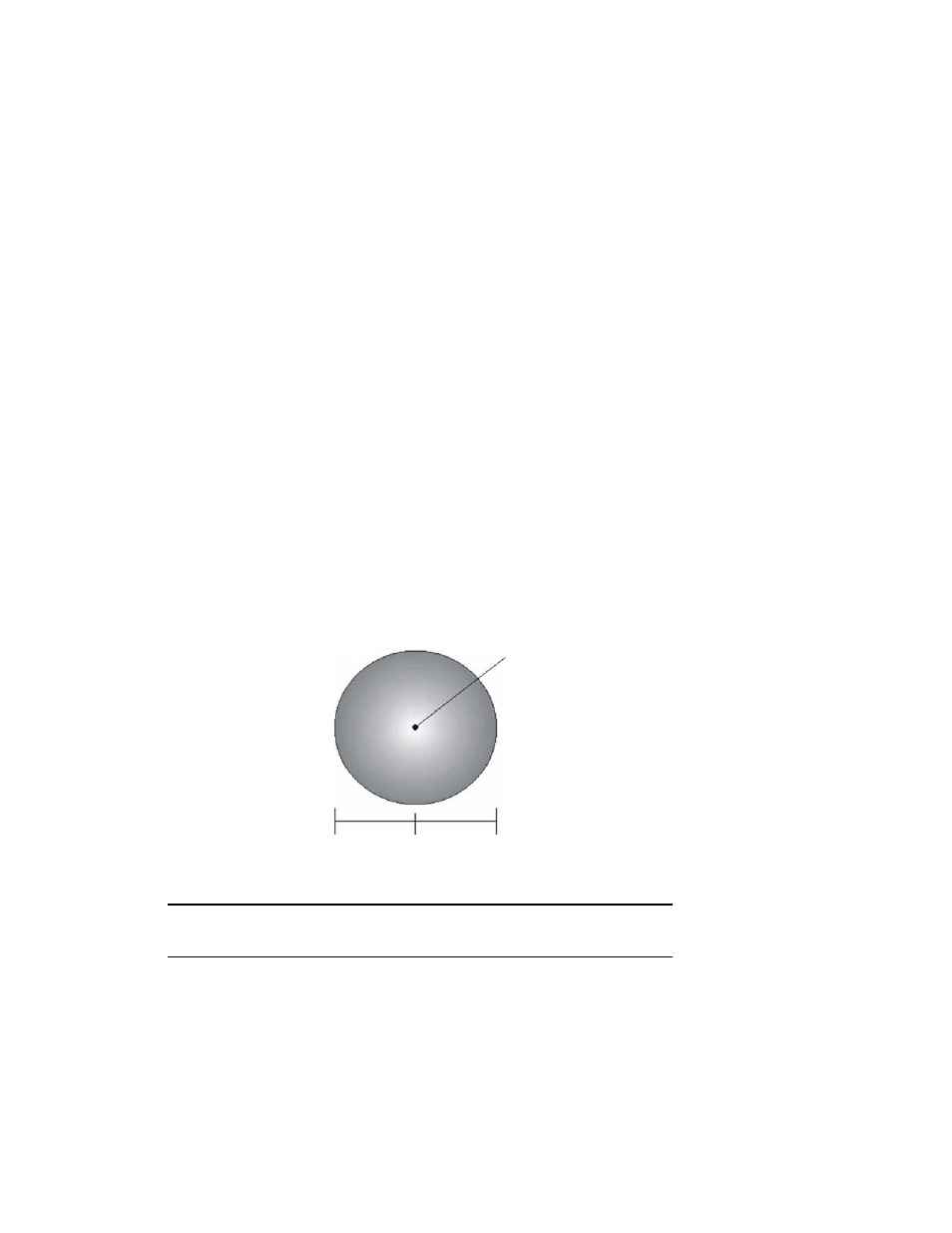
The 3D restricts the RTK solution. It does this knowing that the secondary GPS antenna is 0.27 m (0.89 ft)
from the primary GPS antenna. This is called a fixed baseline and it defines the search volume of the
secondary antenna as the surface of a sphere with radius 0.27 m (0.89 ft) centered on the location of the
primary antenna (see Figure 3-1)
.
Primary antenna
0.27 m
baseline
Figure 3-1: Secondary antenna’s search volume
Note: The Vector 3D moving base station algorithm only uses GPS to calculate heading. Differential
corrections are not used in this calculation and will not affect heading accuracy.
Supplemental Sensors
The 3D has an integrated gyro and two tilt sensors. The gyro and tilt sensors are enabled by default. Each
supplemental sensor may be individually enabled or disabled. Both supplemental sensors are mounted on
the printed circuit board inside the 3D.
The sensors act to reduce the RTK search volume, which improves heading startup and reacquisition times.
This improves the reliability and accuracy of selecting the correct heading solution by eliminating other
possible, erroneous solutions. Table 3-1 on page 24 provides a sensor operation summary
.