Seiwa Si-Tex Vector 3D GPS User Manual
Page 47
54
50
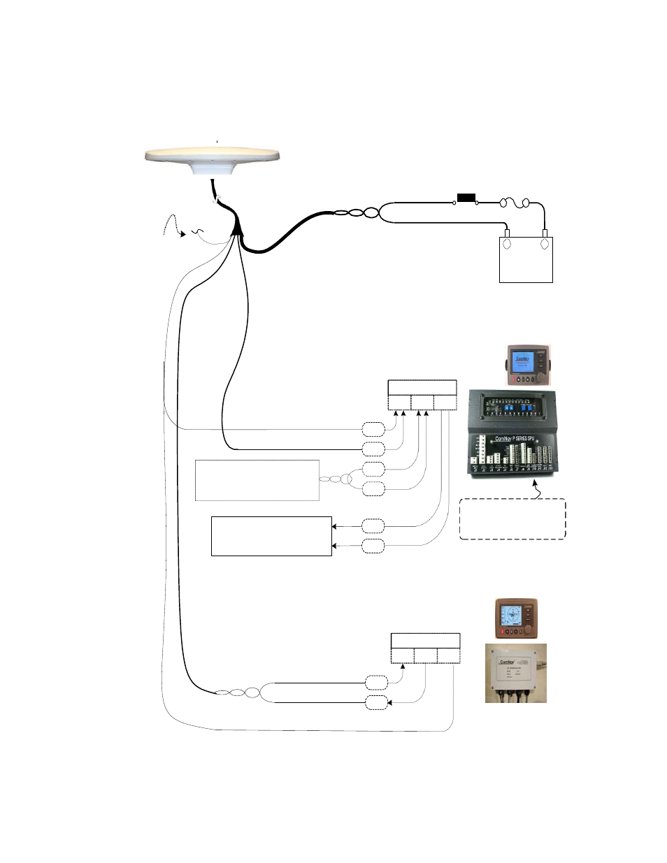
PORTC
Signal Ground
Vector 3D User Guide
Vector 3D
RED(18 AWG)
Power
Switch
Fuse
or Breaker
BLACK(18 AWG)
Cut off &tape back
Shield Drain &
green wire
-
Ship
’s
+
Battery
11
– 36 VDC
PORT C
Autopilot System
(Commander P2 shown)
NMEA0183
YELLOW
(when configured
to 0183)
Signal Ground
In-1
B
In-2 Out
WHITE
A
FromNavigation System
B
&/or other NMEAequipment
A
To Navigation SystemController
B
&/or other NMEAequipment
A
Heading Source : NAVIN1
Speed Source : NAVIN1
Navigation Source : NAVIN2
GPSCompass Display System
(Navigator G2 shown)
Port A(RS-232)
BLUE
BLACKw/ BLUESTRIPE
RS-232
Rx
Tx Gnd
Tx
Rx
YELLOW
Signal Ground
Figure 1 - Typical Wiring Diagram of a Vector 3D System with Autopilot & Compass Display