Seiwa Si-Tex Vector 3D GPS User Manual
Page 20
21
19
Chapter 2: Installation
The receiver end of the cable is terminated with an environmentally sealed 12-pin connection while the
opposite end is unterminated and requires field stripping and tinning.
Depending on the application and installation needs, you may need to shorten this cable. However, if you
require a longer cable run than 15 m, you can bring the cable into a break-out box that incorporates terminal
strips, within the vessel.
When lengthening the cable keep the following in mind:
•
To lengthen the serial lines inside the vessel, use 20-gauge twisted pairs and minimize the
additional wire length.
•
When lengthening the power input leads to the 3D, ensure the additional voltage drop is small
enough that your power system can continue to power the system above the minimum voltage of
the system. Wire of 18-gauge or larger should also be used.
•
Length limits for RS-232 cables
Power/Data Cable Pinout Specifications
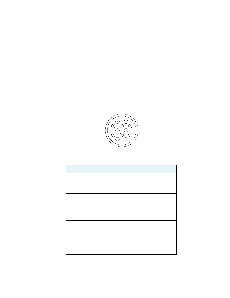
Figure 2-10 show the power/data cable plug pinout while Table 2-4 shows the cable’s pinout specifications
.
Figure 2-10: Power/data cable pin assignment
Table 2-4: Power/data cable pinout
Pin
Function
Wire Color
1
Port C, RS-232 female DB9 pin 2, device out (Tx)
White
2
Port C, RS-232 female DB9 pin 3, device in (Rx)
Green
3
N/C
N/C
4
N/C
N/C
5
Power input
Red
6
N/C
N/C
7
Signal ground
Yellow
8
Port A, RS-232 female DB9 pin 3, device in (Rx)
Brown
9
Port A, RS-232 female DB9 pin 2, device out (Tx)
Blue
10
Power ground
Black
11
CH_GND
Drain
12
N/C
N/C