Seiwa Si-Tex Vector 3D GPS User Manual
Page 24
27
24
Vector 3D User Guide
Feature
Normal Operation
Coasting (no GPS)
Heading
GPS
Gyro
Heave
GPS
None
Pitch
GPS
Inertial sensor
Roll
Inertial sensor
Inertial sensor
Table 3-1: Sensor operation summary
Sensors can be recalibrated, queried, or disabled by some NMEA-like sentences. See descriptions in
Messages and Configuration Commands.
Tilt Aiding
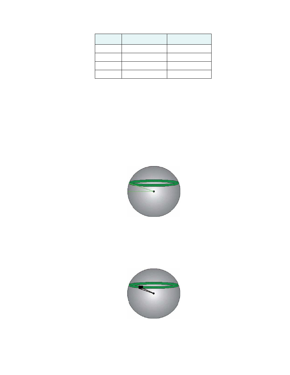
The 3D’s accelerometers (internal tilt sensors) are factory calibrated and enabled by default. This constrains
the RTK heading solution beyond the volume associated with just a fixed antenna separation. This is
because the 3D knows the approximate inclination of the secondary antenna with respect to the primary
antenna. The search space defined by the tilt sensor will be reduced to a horizontal ring on the sphere’s
surface by reducing the search volume. This considerably decreases startup and reacquisition times. (See
Figure 3-2
)
Tilt angle
Figure 3-2: Vector 3D’s tilt aiding
Gyro Aiding
The 3D’s internal gyro offers several benefits. It reduces the sensor volume for an RTK solution. This
shortens reacquisition times when a GPS heading is lost because the satellite signals were blocked. The gyro
provides a relative change in angle since the last computed heading, and, when used in conjunction with the
tilt sensor, defines the search space as a wedge-shaped location. (See Figure 3-3
)
Figure 3-3: Vector 3D’s gyro aiding
The gyro aiding accurately smoothes the heading output and the rate of turn. It provides an accurate
substitute heading for a short period depending on the roll and pitch of the vessel, ideally seeing the system
through to reacquisition. The gyro provides an alternate source of heading, accurate to within 1º for up to
three minutes, in times of GPS loss for either antenna. If the outage lasts longer than three minutes, the gyro