Powering the 3d, Connecting the 3d to external devices – Seiwa Si-Tex Vector 3D GPS User Manual
Page 19
20
18
Vector 3D User Guide
Powering the 3D
Power Considerations
For best performance use a clean and continuous power supply. The 3D power supply features reverse
polarity protection but will not operate with reverse polarity.
See Table B-3 on page 53 for complete power specifications.
Connecting to a Power Source
Note: This section refers to powering the unit via serial connection. To power the unit via NMEA 2000
connection, following the standard procedure for powering up via NMEA 2000.
Before you power up the 3D you must terminate the wires of the power cable as required. There are a variety
of power connectors and terminals on the market from which to choose, depending on your specific
requirements.
warranty.
Do not apply a voltage higher than 36 VDC. This will damage the receiver and void the
To interface the 3D power cable to the power source:
•
Connect the red wire of the cable’s power input to DC positive (+)
•
Connect the black wire of the cable’s power input to DC negative (-)
The 3D’s smart antenna will start when an acceptable voltage is applied to the power leads of the extension
cable.
Electrical Isolation
The 3D’s power supply is isolated from the communication lines and the PC-ABS plastic enclosure isolates
the electronics mechanically from the vessel (addressing the issue of vessel hull electrolysis).
Connecting the 3D to External Devices
Note: This section refers to a serial connection. For connecting external NMEA 2000 devices, plug the
serial-to-NMEA 2000 adapter into the 3D and then attach a standard NMEA 2000 dropline cable to the
adapter.
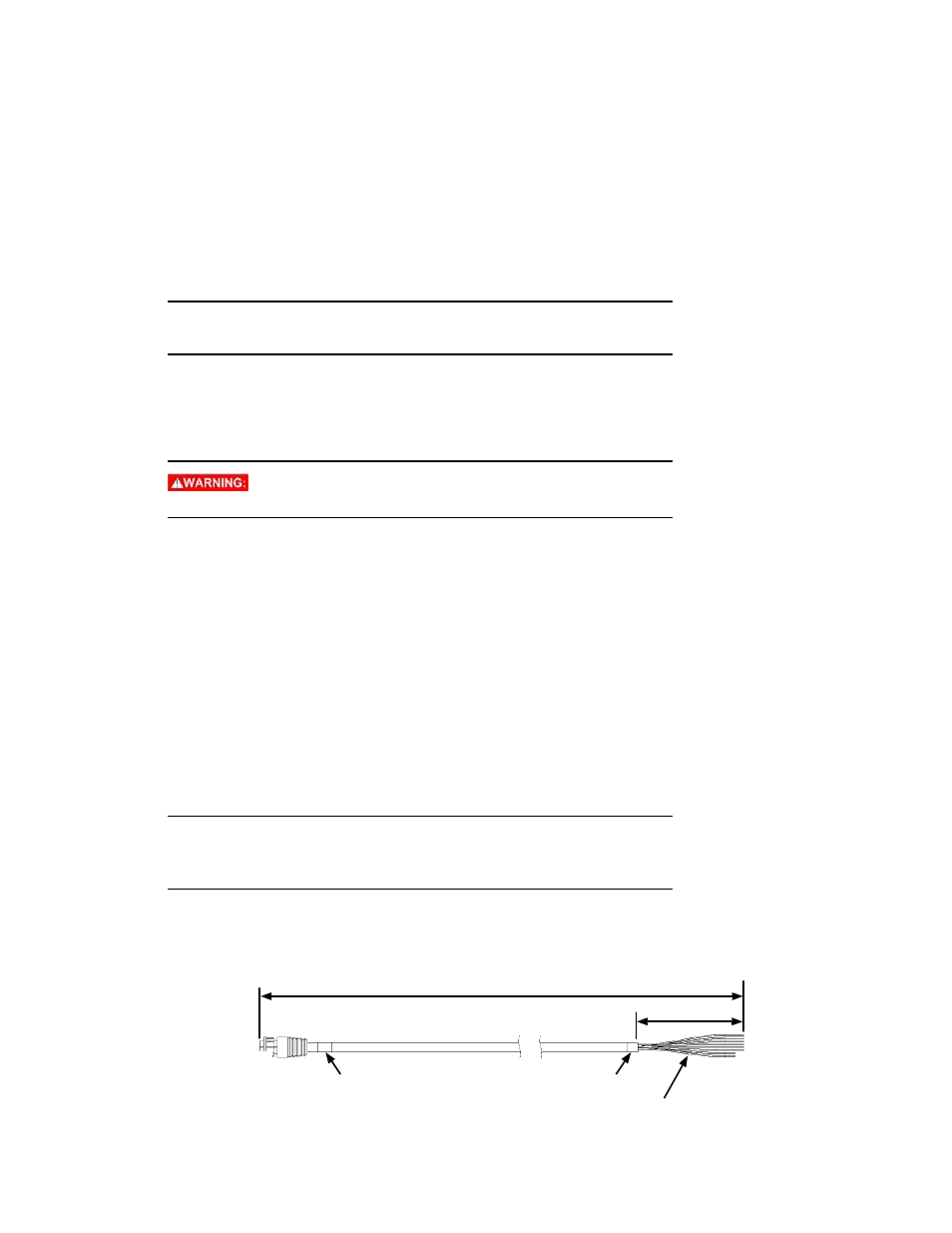
Power/Data Cable Considerations
The 3D uses a single 15 m (49 ft) cable for power and data input/output.
15 m
100 mm
J1
P1
30 mm
25 mm
Strip and tin 3 mm
Figure 2-9: Power/data cable, 15 m