Pfannenberg DTI 6x01 User Manual
Page 14
GB
085 408 121a
14/60
• No temperature control must be series-connected to the cooling
unit feed.
The fuse as indicated on the ID plate must be series-connected
as line protection.
• Power connection and repairs, if applicable, may only be carried
out by authorized trained electricians.
Power supply connection (mains):
Both mains voltage and frequency must correspond to the nominal
values indicated on the ID plate of the cooling unit.
• The installation of the power cable is not subject to any special
requirements
Attention: The cooling unit may be damaged if the
voltage is too high.
Refers to cooling units for nominal voltages 400 V/460V.
As an option, some units, different to the standard (400
V/460 V), may be connected to a different mains voltage
(For voltage range see enclosed sheet).The feed cables on
the transformer primary must be unclamped for this.
Attention! The cooling unit may be damaged due to
incorrect direction of rotation.
Before switching on the unit, check the phase sequence of
the three-phase supply in order to prevent damage to the
compressor. Direction of rotation must be to the right
(clockwise). The correct pin assignment is indicated by an il-
luminated LED in the connection area. With a flashing or
dark LED the pin assignment must be checked.
Door contact:
The door contact is supplied form the cooling unit with an extra-low
voltage (<20V, 20 mA).
• In order to avoid any disruptive influences, it is recommended
that a sheathed cable with twisted pair leads be used. The
screen can be secured on one side to the PE connection point
provided on the cooling unit.
• If the use of sheathed cables is not possible, during installation of
the cables it must be ensured that they are not routed in the im-
mediate vicinity of potential interference sources (e.g. supply
lines, components with relatively high electromagnetic emission).
WARNING: No external voltage may be applied
If no door-contact switch is used, the connecting contacts
are to be bridged.
Centralised fault indication:
For connection of the fault signal line there are 2 connection con-
tacts and/or connecting lines available (see circuit diagram on the
Technical Supplementary Sheet)
The installation of the fault signal line is not subject to any special
requirements.
WARNING: The contact may be loaded with max.
230 V, 1A.
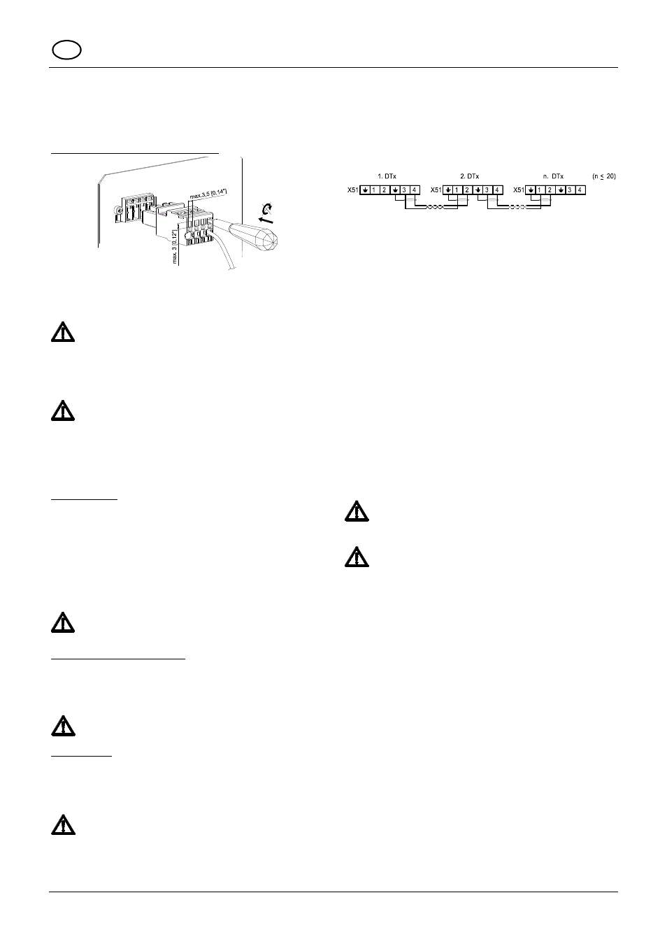
Multimaster:
(Optional, only for units with Multi-Controller)
To connect the multimaster cables there are in each case 2 con-
necting contacts (input and output-end) available (see connecting
diagram on the rear of the housing).
The contacts are supplied with low voltage (< 20 V, 20 mA) from the
cooling unit.
WARNING: No external voltage may be applied
• In order to avoid any disruptive influences, it is recommended
that a sheathed cable with twisted pair leads be used. The
sheath can be connected at both ends to the PE terminal pro-
vided on the cooling unit for the purpose.
• If the use of sheathed cables is not possible, during installation of
the cables it must be ensured that they are not routed in the im-
mediate vicinity of potential interference sources (e.g. supply
lines, components with relatively high electromagnetic emission).
• A maximum of 20 units may be controlled over the bus.
Block diagram of the Multimaster wiring
For more information see also chapter 10.8 (Multimaster – bus)
9 Operating Conditions
• Voltage must be within ± 10 % of the value indicated.
Frequency must be within ± 3 Hz of the value indicated.
• Ambient temperature must be below 55 °C (for options see
supplement).
• Use the unit such that the cooling capacity suits the actual de-
mand.
• Use refrigerant as indicated only.
• Use genuine spare parts only.
10 Putting into operation and function
10.1 General remarks
The cooling unit is provided with an electronic control system. The
drawn-in switch cabinet internal air temperature is measured by a
temperature sensor. By means of a DIP switch on the control board,
different switch cabinet temperatures as well as upper limit tempera-
tures can be selected (see accompanying supplement sheet). With
devices with Multi-Controller the adjustment takes place by means
of a USB cable and the configuration software ECoolPLANT, includ-
ing the USB driver software. Exceeding the limit temperature gener-
ates an alarm. For units with Multi-Controller, the lower temperature
limit can also be monitored.
Warning!
Ambient conditions and temperature in the switch cabinet
must be in accordance with the values indicated in the sup-
plement.
Warning! Too little heat transfer at the heat exchanger
in the external circuit (condenser)..
The cooling unit may only be operated with cover, otherwise
heat dissipation at the condenser is not sufficient, and the
cooling unit may be damaged.
Immediately after the switch-on of the service voltage, the
unit goes into the start-up/test mode. After that the evapora-
tor fan continues to run. Compressor and condenser fans
run on as required (the temperature of the switching thresh-
old (T
set
) has been reached, or are switched off (temperature
lower than switching threshold (T
set
)).
• Free discharge of any condensate produced must be provided to
ensure trouble-free operation.
10.2 Indicator elements
The cooling unit with standard controller has an operational display
in the form of an LED on the external hood of the unit. If the light of
this indicator remains on when the supply voltage is applied it shows
that the unit is in the normal operating mode. If a fault occurs or if
the unit is in the start-up or test mode, this indicator lights up in
various flashing sequences which make it easier to diagnose fault in
the unit (see Sections 10.4 and 13)
The cooling unit with multicontroller has a temperature display.
10.3 Test mode / start-up
The test mode is basically activated after renewed connection of the
supply voltage and is independent of the instantaneous ambient
conditions when the door contact is closed.
First of all the unit runs through a start-up mode lasting 30 seconds
which is followed by a test mode lasting 30 seconds.