Cirrus Logic CS8415A User Manual
Cs8415a, 96 khz digital audio interface receiver, Features
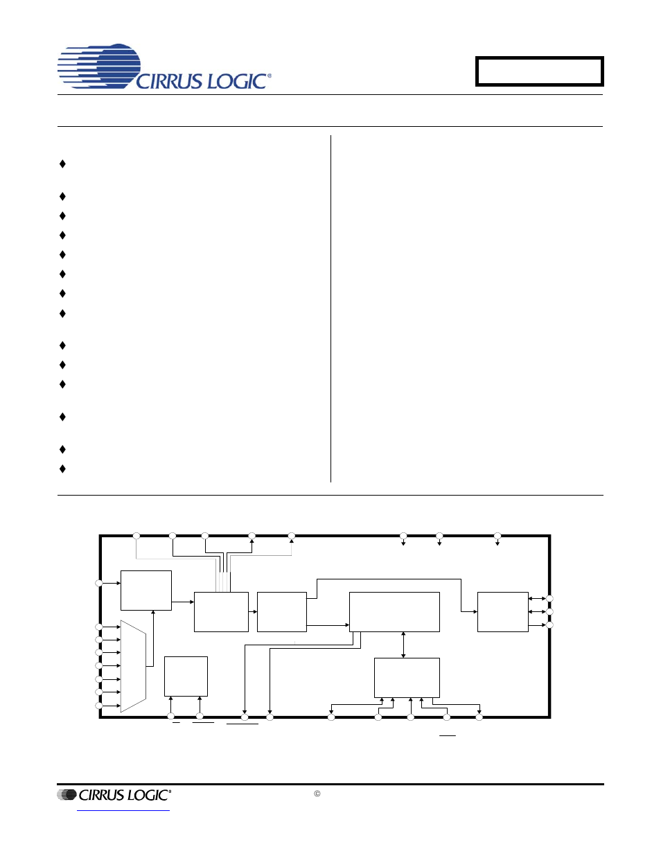
Table of contents
Document Outline
- 1. Characteristics and Specifications
- Specified Operating Conditions
- Absolute Maximum Ratings
- DC Electrical Characteristics
- Digital Input Characteristics
- Digital Interface Specifications
- Switching Characteristics
- Switching Characteristics - Serial Audio Ports
- Switching Characteristics - Control Port - SPI Mode
- Switching Characteristics - Control Port - I·C Mode
- 2. Typical Connection Diagram
- 3. General Description
- 4. Serial Audio output Port
- 5. AES3 Receiver
- 6. Control Port Description and Timing
- 7. Control Port Register Summary
- 8. Control Port Register Bit Definitions
- 8.1 Control 1 (01h)
- 8.2 Control 2 (02h)
- 8.3 Clock Source Control (04h)
- 8.4 Serial Audio Output Port Data Format (06h)
- 8.5 Interrupt 1 Status (07h) (Read Only)
- 8.6 Interrupt 2 Status (08h) (Read Only)
- 8.7 Interrupt 1 Mask (09h)
- 8.8 Interrupt 1 Mode MSB (0Ah) and Interrupt 1 Mode LSB (0Bh)
- 8.9 Interrupt 2 Mask (0Ch)
- 8.10 Interrupt 2 Mode MSB (0Dh) and Interrupt 2 Mode LSB (0Eh)
- 8.11 Receiver Channel Status (0Fh) (Read Only)
- 8.12 Receiver Error (10h) (Read Only)
- 8.13 Receiver Error Mask (11h)
- 8.14 Channel Status Data Buffer Control (12h)
- 8.15 User Data Buffer Control (13h)
- 8.16 Q-Channel Subcode Bytes 0 to 9 (14h - 1Dh) (Read Only)
- 8.17 OMCK/RMCK Ratio (1Eh) (Read Only)
- 8.18 C-bit or U-bit Data Buffer (20h - 37h)
- 8.19 CS8415A I.D. and Version Register (7Fh) (Read Only)
- 9. Pin Description - Software Mode
- 10. Hardware Mode
- 11. Pin Description - Hardware Mode
- 12. Applications
- 13. Appendix A: External AES3/SPDIF/IEC60958 Receiver Components
- 14. Appendix B: Channel Status and User Data Buffer Management
- 15. Appendix C: PLL Filter
- 16. Revision History