3 component value selection, 1 identifying the part revision, Table 4. second line part marking – Cirrus Logic CS8415A User Manual
Page 43: 2 external components, Table 5. fs = 8 to 96khz, Table 6. fs = 32 to 96khz, Table 6, Table 5, Cs8415a
DS470F4
43
CS8415A
15.3
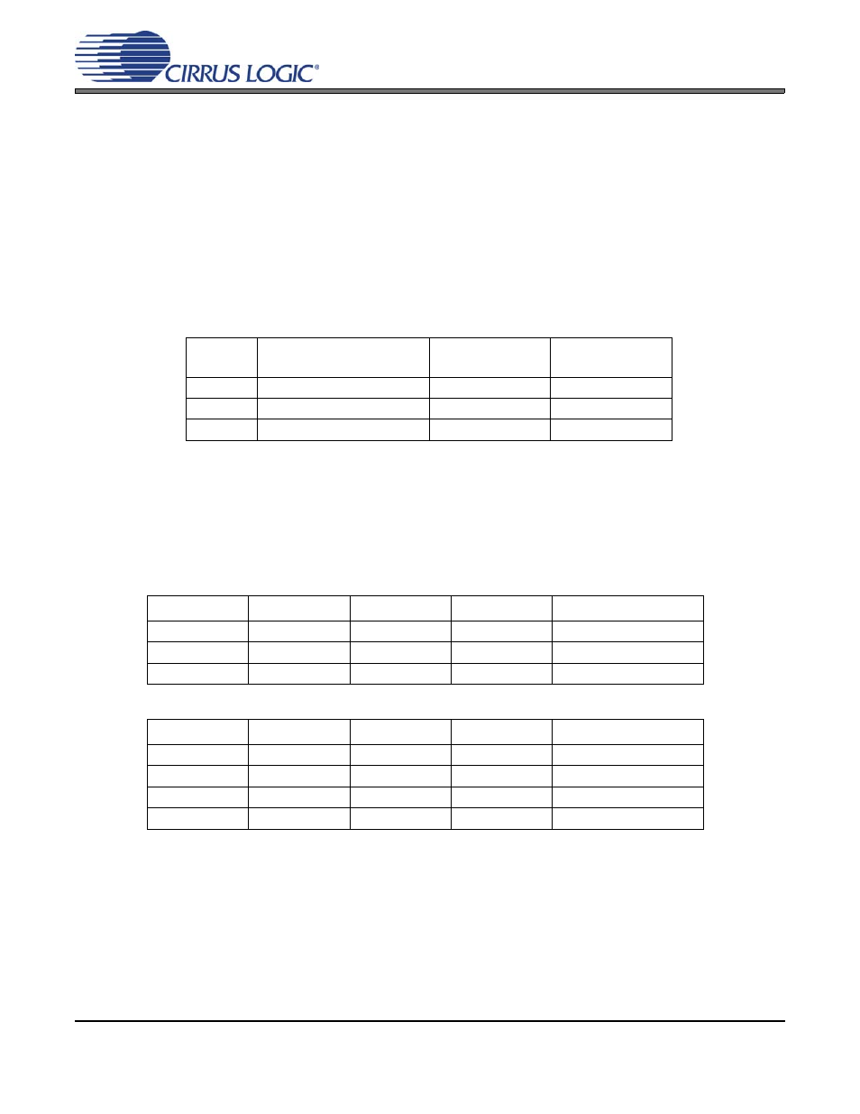
Component Value Selection
When transitioning from one revision of the part another, component values may need to be changed. While
it is mandatory for customers to change the external PLL component values when transitioning from revision
A to revision A1 or from revision A to revision A2, customers do not need to change external PLL component
values when transitioning from revision A1 to revision A2, unless the part is used in an application that is
required to pass the AES3 or IEC60958-4 specification for receiver jitter tolerance (see
15.3.1
Identifying the Part Revision
The first line of the part marking on the package indicates the part number and package type (CS8415A-
xx).
shows a list of part revisions and their corresponding second line part marking, which indi-
cates what revision the part is.
15.3.2
External Components
and
are the external PLL component values for each revision. Values listed for
the 32 to 96 kHz Fs range will have the highest corner frequency jitter attenuation curve, take the shortest
time to lock, and offer the best output jitter performance.
Revision
Pre-October 2002
SOIC & TSSOP (10-Digit)
New SOIC
(12-Digit)
New TSSOP
(10-Digit)
A
Zxxxxxxxxx
ZFBAAXxxxxxx
NAAXxxxxxx
A1
Rxxxxxxxxx
RFBAA1xxxxxx
NAA1xxxxxx
A2
N/A
RFBAA2xxxxxx
NAA2xxxxxx
Table 4. Second Line Part Marking
Revision
R
FILT
(k
Ω)
C
FILT
(
µF)
C
RIP
(nF)
PLL Lock Time (ms)
A
0.909
1.8
33
56
A1
0.4
0.47
47
60
A2
0.4
0.47
47
60
Table 5. Fs = 8 to 96 kHz
Revision
R
FILT
(k
Ω)
C
FILT
(
µF)
C
RIP
(nF)
PLL Lock Time (ms)
A*
3.0
0.047
2.2
35
A1*
1.2
0.1
4.7
35
A2
1.2
0.1
4.7
35
A2*
1.6
0.33
4.7
35
Table 6. Fs = 32 to 96 kHz
* Parts used in applications that are required to pass the AES3 or IEC60958-4 specifica-
tion for receiver jitter tolerance should use these component values. Please note that the
AES3 and IEC60958 specifications do not have allowances for locking to sample rates
less than 32 kHz. Also note that many factors can affect jitter performance in a system.
Please follow the circuit and layout recommendations outlined previously