Cirrus Logic CS8406 User Manual
Cs8406, 192 khz digital audio interface transmitter, Features
Copyright
Cirrus Logic, Inc. 2012
(All Rights Reserved)
192 kHz Digital Audio Interface Transmitter
Features
Complete EIAJ CP1201, IEC-60958, AES3,
S/PDIF-compatible Transmitter
+3.3 V or 5.0 V Digital Supply (VD)
+3.3 V or 5.0 V Digital Interface (VL)
On-Chip Channel Status and User Bit Buffer
Memories Allow Block-Sized Updates
Flexible 3-Wire Serial Digital Audio Input Port
Up to 192-kHz Frame Rate
Microcontroller Write Access to Channel Status
and User Bit Data
On-Chip Differential Line Driver
Generates CRC Codes and Parity Bits
Stand-Alone Mode Allows Use without a
Microcontroller
General Description
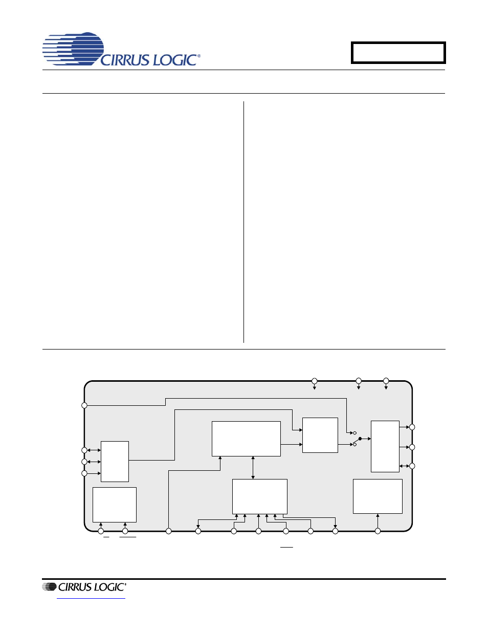
The CS8406 is a monolithic CMOS device which en-
codes and transmits audio data according to the AES3,
IEC60958, S/PDIF, o r EIAJ CP1201 standards. The
CS8406 accepts audio and digital data, which is then
multiplexed, encoded, and driven onto a cable.
The audio data is input through a configurable, 3-wire
input port. The channel status and user bit data are in-
put through an SPI™ or I²C
®
microcontroller port, and
may be assembled in block-sized buffers. For systems
with no microcontroller, a Stand-Alone Mode allows di-
rect access to channel status and user bit data pins.
The CS8406 is available in a 28-pin TSSOP and SOIC
package for both Co mmercial (-10º to +70ºC) and
Automotive grade (-40º to +85ºC). The CDB8416
Demonstration board is also available for device
evaluation and implementation suggestions. Please
refer to
“Ordering Information” on page 34
for complete
details.
Target applications include A/V Receivers, CD-R, DVD
receivers, digital mixin g consoles, effects processors,
set-top boxes, and computer and automotive audio
systems.
RXP
ILRCK
ISCLK
SDIN
TXP
TXN
RST
OMCK
U
SDA/
CDOUT
SCL/
CCLK
AD1/
CDIN
AD0/
CS
INT
VL
GND
AD2
H/S
VD
TCBL
Misc.
Control
Serial
Audio
Input
C or U Data Buffer
Control Port &
Registers
AES3
S/PDIF
Encoder
Output Clock
Generator
Driver
AUG '12
DS580F6
CS8406
Document Outline
- 1. Characteristics and Specifications
- Specified Operating Conditions
- Absolute Maximum Ratings
- DC Electrical Characteristics
- Digital Input Characteristics
- Digital Interface Specifications
- Transmitter Characteristics
- Switching Characteristics
- Switching Characteristics - Serial Audio Ports
- Switching Characteristics - Control Port - SPI Mode
- Switching Characteristics - Control Port - I·C Mode
- 2. Typical Connection Diagrams
- 3. General Description
- 4. Three-Wire Serial Input Audio Port
- 5. AES3 Transmitter
- 6. Control Port Description
- 7. Control Port Register Summary
- 8. Control Port Register Bit Definitions
- 8.1 Memory Address Pointer (MAP)
- 8.2 Default = ‘000000’Control 1 (01h)
- 8.3 Control 2 (02h)
- 8.4 Data Flow Control (03h)
- 8.5 Clock Source Control (04h)
- 8.6 Serial Audio Input Port Data Format (05h)
- 8.7 Interrupt 1 Status (07h) (Read Only)
- 8.8 Interrupt 2 Status (08h) (Read Only)
- 8.9 Interrupt 1 Mask (09h)
- 8.10 Interrupt 1 Mode MSB (0Ah) and Interrupt 1 Mode LSB (0Bh)
- 8.11 Interrupt 2 Mask (0Ch)
- 8.12 Interrupt 2 Mode MSB (0Dh) and Interrupt Mode 2 LSB (0Eh)
- 8.13 Channel Status Data Buffer Control (12h)
- 8.14 User Data Buffer Control (13h)
- 8.15 Channel Status Bit or User Bit Data Buffer (20h - 37h)
- 8.16 CS8406 I.D. and Version Register (7Fh) (Read Only)
- 9. Pin Description - Software Mode
- 10. Hardware Mode
- 11. Pin Description - Hardware Mode
- 12. Applications
- 13. Package Dimensions
- 14. Ordering Information
- 15. Appendix A: External AES3/SPDIF/IEC60958 Transmitter Components
- 16. Appendix B: Channel Status and User Data Buffer Management
- 17. Revision History