Pin description - hardware mode – Cirrus Logic CS8406 User Manual
Page 29
DS580F6
29
CS8406
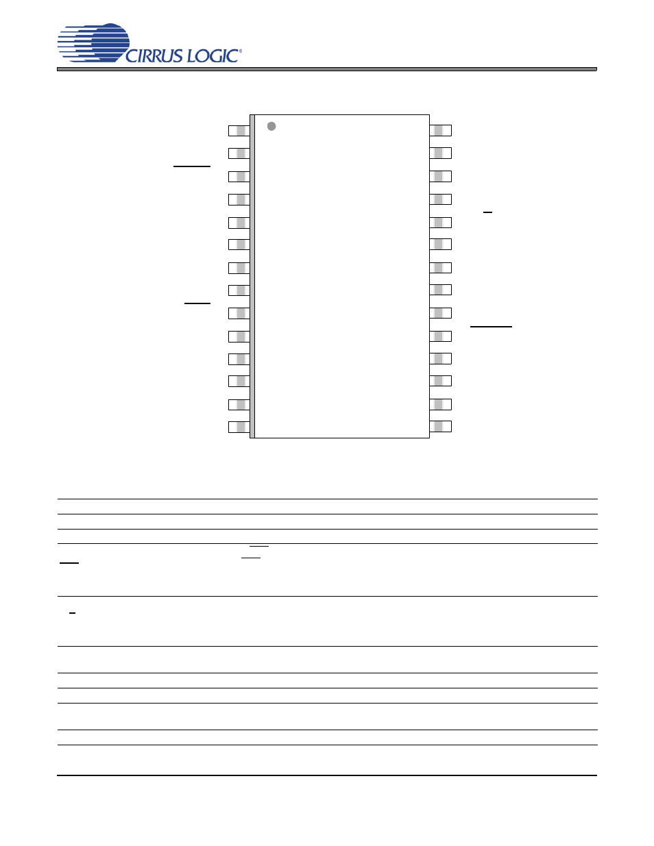
11.PIN DESCRIPTION - HARDWARE MODE
VD
6
Digital Power (Input) - Digital core power supply. Typically +3.3 V or +5.0 V.
VL
23
Logic Power (Input) - Input/Output power supply. Typically +3.3 V or +5.0 V.
GND
22
Ground (Input) - Ground for I/O and core logic.
RST
9
Reset (Input) - When RST is low, the CS8406 enters a low power mode and all internal states are reset.
On initial power up, RST must be held low until the power supply is stable, and all input clocks are stable
in frequency and phase. This is particularly true in Hardware Mode with multiple CS8406 devices, where
synchronization between devices is important.
H/S
24
Hardware/Software Control Mode Select (Input) - Determines the method of controlling the operation
of the CS8406, and the method of accessing CS and U data. Hardware Mode provides an alternate
mode of operation, and access to CS and U data is provided by dedicated pins. To select Hardware
Mode, this pin should be permanently tied to VL.
TXN
TXP
25
26
Differential Line Drivers (Output) - These pins transmit biphase encoded data. The drivers are pulled
low while the CS8406 is in the reset state.
OMCK
21
Master Clock (Input) - The frequency can be set through the HWCK[1:0] pins.
ISCLK
13
Serial Audio Bit Clock (Input/Output) - Serial bit clock for audio data on the SDIN pin.
ILRCK
12 Serial Audio Input Left/Right Clock (
Input
/Output) - Word rate clock for the audio data on the SDIN
pin.
SDIN
14
Serial Audio Data Port (Input) - Audio data serial input pin.
COPY / C
ORIG
TEST
HWCK1
EMPH
TXP
SFMT0
TXN
SFMT1
H/S
VD
VL
TEST
GND
TEST
OMCK
RST
HWCK0
APMS
AUDIO
TCBLD
U
ILRCK
V
ISCLK
CEN
SDIN
TCBL
1
2
3
4
5
6
7
8
21
22
23
24
25
26
27
28
9
10
11
12
17
18
19
20
13
14
15
16