Hardware mode, 1 channel status, user and validity data, Figure 13. hardware mode data flow – Cirrus Logic CS8406 User Manual
Page 27
DS580F6
27
CS8406
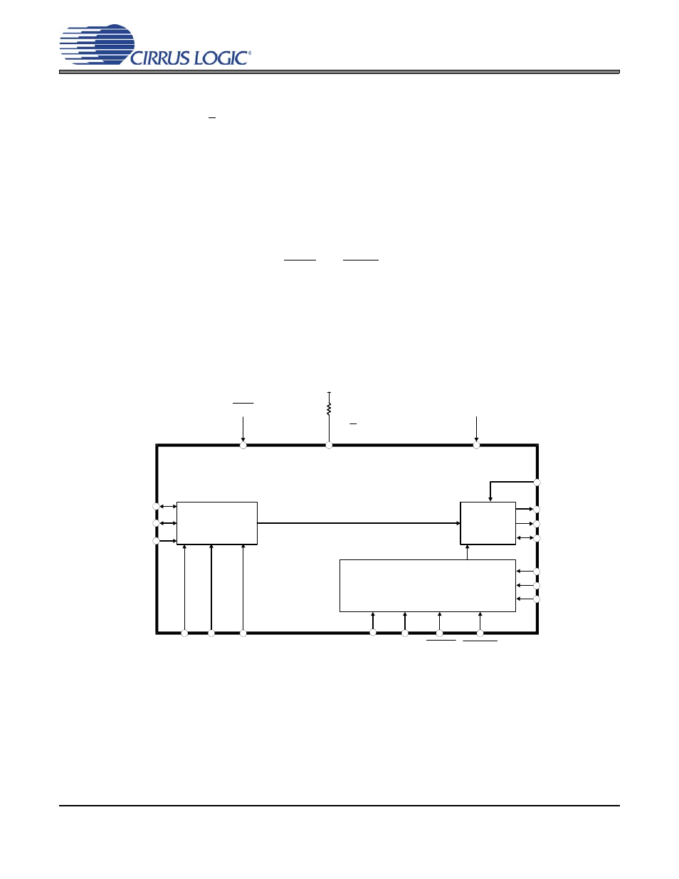
10.HARDWARE MODE
The CS8406 has a Hardware Mode that allows the use of the device without a microcontroller. Hardware Mode is
selected by connecting the H/S pin to VL. The flexibility of the CS8406 is necessarily limited in Hardware Mode.
Various pins change function as described in the Hardware Mode pin description section.
The Hardware Mode data flow is shown in
. Audio data is input through the serial audio input port and rout-
ed to the AES3 transmitter.
10.1 Channel Status, User and Validity Data
The transmitted channel status, user and validity data can be input in two methods, determined by the state
of the CEN pin. Mode A is selected when the CEN pin is low. In Mode A, the user bit data and the validity
bit are input through the U and V pins, clocked by both edges of ILRCK. The channel status data is derived
from the state of the COPY/C, ORIG, EMPH, and AUDIO pins.
pins map to channel status bits. In Consumer Mode, the transmitted category code is set to General (00h).
Mode B is selected when the CEN pin is high. In Mode B, the channel status, user data bits and the validity
bit are input serially through the COPY/C, U and V pins. Data is clocked into these pins at both edges of
shows the timing requirements.
AES3
Encoder
& Tx
Serial
Audio
Input
C, U, V Data Buffer
ILRCK
ISCLK
TXP
COPY/C ORIG EMPH AUDIO
VL
H/S
Output
Clock
Source
OMCK
Power supply pins are omitted from this diagram.
Please refer to the Typical Connection Diagram for hook-up details.
SDIN
SFMT1 SFMT0
TXN
CEN
U
V
APMS
TCBL
TCBLD
RST
Figure 13. Hardware Mode Data Flow