Three-wire serial input audio port, Figure 7. serial audio input example formats – Cirrus Logic CS8406 User Manual
Page 12
12
DS580F6
CS8406
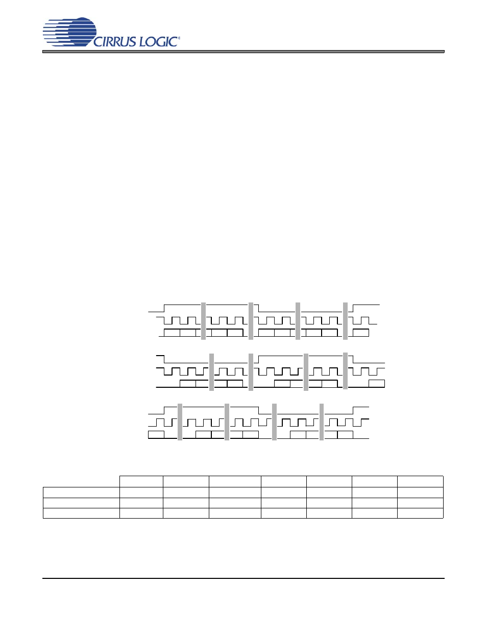
4. THREE-WIRE SERIAL INPUT AUDIO PORT
A 3-wire serial audio input port is provided. The interface format can be adjusted to suit the attached device through
the control registers. The following parameters are adjustable:
• Master or slave
• Serial clock frequency
• Audio data resolution
• Left or right justification of the data relative to left/right clock
• Optional one-bit cell delay of the first data bit
• Polarity of the bit clock
• Polarity of the left/right clock (by setting the appropriate control bits, many formats are possible.)
shows a selection of common input formats with the corresponding control bit settings.
In Master Mode, the left/right clock and the serial bit clock are outputs, derived from the OMCK input pin master
clock.
In Slave Mode, the left/right clock and the serial bit clock are inputs. The left/right clock must be synchronous to the
OMCK master clock, but the serial bit clock can be asynchronous and discontinuous if required. The left/right clock
should be continuous, but the duty cycle can be less than the specified typical value of 50% if enough serial clocks
are present in each phase to clock all the data bits.
ILRCK
ISCLK
SDIN
2
Left
Justified
(In)
MSB
LSB
Left
Right
MSB
I S
(In)
Right
Justified
(In)
MSB
LSB
MSB
LSB
MSB
Left
Right
MSB
LSB
MSB
LSB
Left
Right
LSB
MSB
LSB
ILRCK
ISCLK
SDIN
ILRCK
ISCLK
SDIN
Figure 7. Serial Audio Input Example Formats
X = don’t care to match format, but does need to be set to the desired setting
+ I²S can accept an arbitrary number of bits, determined by the number of ISCLK cycles
* See Serial Input Port Data Format Register Bit Descriptions for an explanation of the meaning of each bit
SIMS*
SISF*
SIRES[1:0]*
SIJUST*
SIDEL*
SISPOL*
SILRPOL*
Left Justified
X
X
00+
0
0
0
0
I²S
X
X
00+
0
1
0
1
Right Justified
X
X
XX
1
0
0
0