7 master clock switching characteristics, 8 transmit switching characteristics, 9 receive switching characteristics – Cirrus Logic CS61880 User Manual
Page 58
CS61880
58
DS450PP3
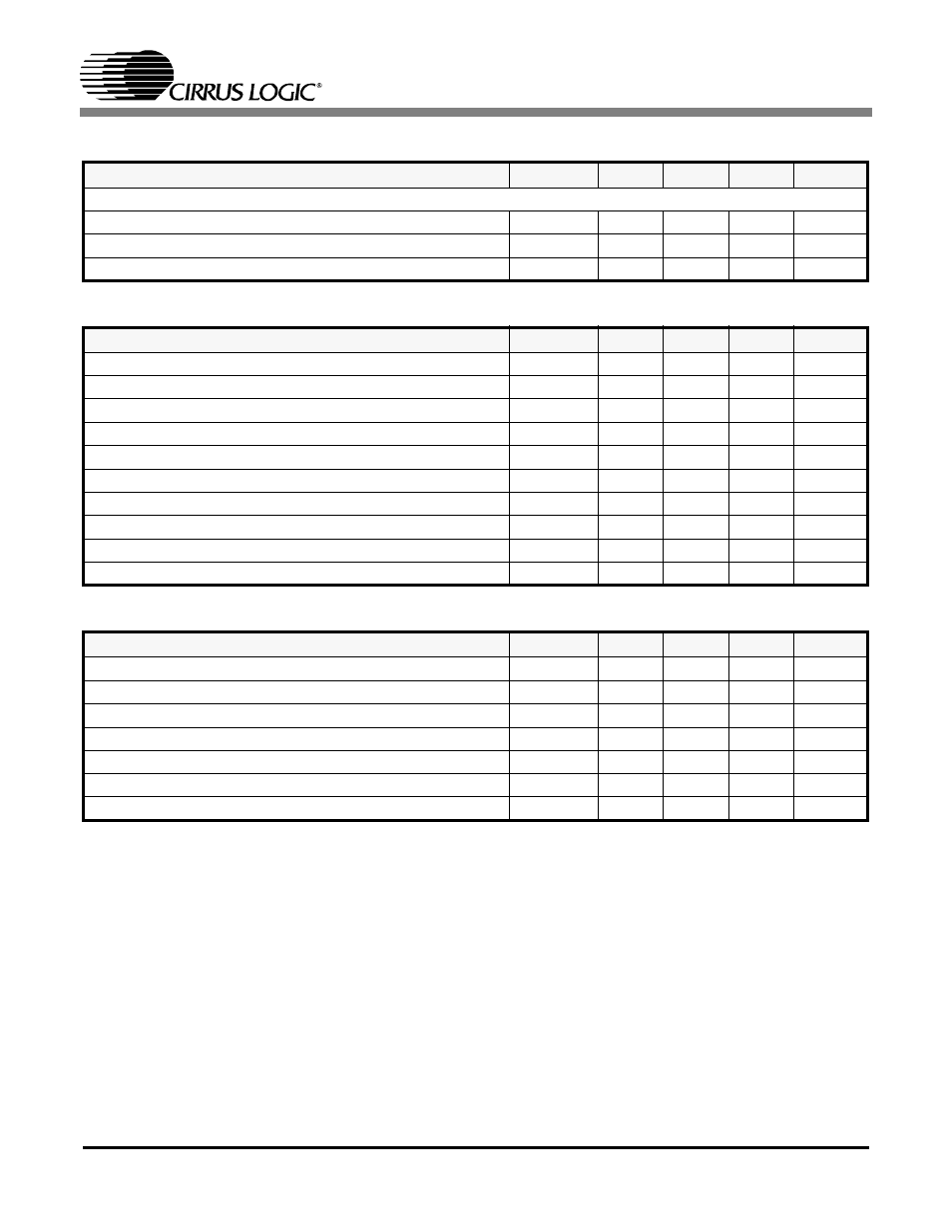
19.7 Master Clock Switching Characteristics
19.8 Transmit Switching Characteristics
19.9 Receive Switching Characteristics
Notes: 19. Output load capacitance = 50 pF.
20. MCLK is not active.
Parameter
Symbol
Min.
Typ
Max
Units
MASTER CLOCK (MCLK)
Master Clock Frequency
MCLK
2.048
MHz
Master Clock Tolerance
-
-100
+100
ppm
Master Clock Duty Cycle
-
40
50
60
%
Parameter
Symbol
Min.
Typ
Max
Units
TCLK Frequency
1/t
pw2
-
2.048
-
MHz
TPOS/TNEG Pulse Width (RZ Mode)
236
244
252
ns
TCLK Tolerance (NRZ Mode)
-50
-
50
PPM
TCLK Duty Cycle
t
pwh2
/t
pw2
-
-
90
%
TCLK Pulse Width
20
-
-
ns
TCLK Burst Rate
Note
10
-
-
20
MHz
TPOS/TNEG to TCLK Falling Setup Time (NRZ Mode)
t
su2
25
-
-
ns
TCLK Falling to TPOS/TNEG Hold time (NRZ Mode)
t
h2
25
-
-
ns
TXOE Asserted Low to TX Driver HIGH-Z
-
-
1
µ
s
TCLK Held Low to Driver HIGH-Z
Note
20
8
12
20
µ
s
Parameter
Symbol
Min.
Typ
Max
Units
RCLK Duty Cycle
Note
10
40
50
60
%
RCLK Pulse Width
Note
10
196
244
328
ns
RPOS/RNEG Pulse Width (RZ Mode)
Note
10
200
244
300
ns
RPOS/RNEG to RCLK rising setup time
Note
10
t
su
200
244
ns
RPOS/RNEG to RCLK hold time
Note
10
t
h
200
244
ns
RPOS/RNEG Output to RCLK Output (RZ Mode)
Note
10
-
-
10
ns
Rise/Fall Time, RPOS, RNEG, RCLK, LOS outputs Note
19
t
r
, t
f
-
-
85
ns