Jitter attenuator, Table 7. jitter attenuator configurations – Cirrus Logic CS61880 User Manual
Page 28
CS61880
28
DS450PP3
11. JITTER ATTENUATOR
The CS61880 internal jitter attenuators can be
switched into either the receive or transmit paths.
Alternatively, it can be removed from both paths to
reduce the propagation delay.
During Hardware mode operation, the location of
the jitter attenuator for all eight channels are con-
trolled by the JASEL pin (Refer to
for pin
configurations). The jitter attenuator’s FIFO length
and corner frequency, can not be changed in hard-
ware mode. The FIFO length and corner frequency
are set to 32 bits and 1.25 Hz.
During host mode operation, the location of the jit-
ter attenuator for all eight channels are set by bits 0
and 1 in the
Line Length Channel ID Register
(See Section 14.17 on page 38). This register
(0Fh) also configures the jitter attenuator’s FIFO
length (bit 3) and corner frequency (bit 2).
The attenuator consists of a 64-bit FIFO, a narrow-
band monolithic PLL, and control logic. The jitter
attenuator requires no external crystal. Signal jitter
is absorbed in the FIFO which is designed to nei-
ther overflow nor underflow.
If overflow or underflow is imminent, the jitter
transfer function is altered to ensure that no bit-er-
rors occur. A configuration option is provided to
reduce the jitter attenuator FIFO length from 64
bits to 32 bits in order to reduce propagation delay.
The jitter attenuator -3 dB knee frequency depends
on the settings of the Jitter Attenuator FIFO length
and the Jitter Attenuator Corner Frequency, bits 2
and 3, in the
Line Length Channel ID Register
(See Section 14.17 on page 38)). Setting the
lowest corner frequency guarantees jitter attenua-
tion compliance to European specifications TBR
12/13 and ETS 300 011. The jitter attenuator is also
compliant with ITU-T G.735, G.742, and G.783
(Refer to
).
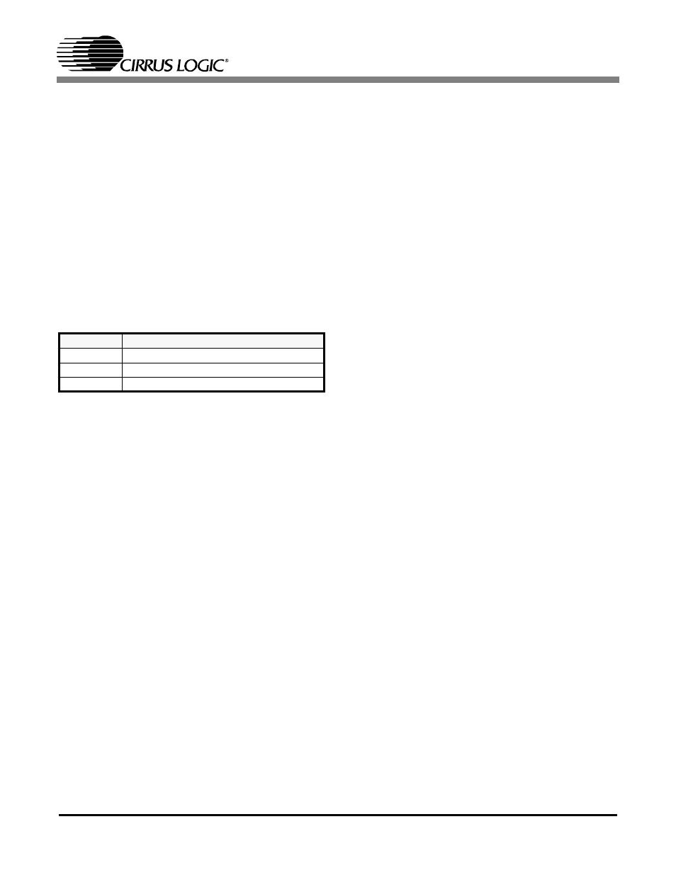
Table 7. Jitter Attenuator Configurations
PIN STATE
JITTER ATTENUATOR POSITON
LOW
Transmit Path
HIGH
Receive Path
OPEN
Disabled