8 pause-dr, 9 exit2-dr, 10 update-dr – Cirrus Logic CS61880 User Manual
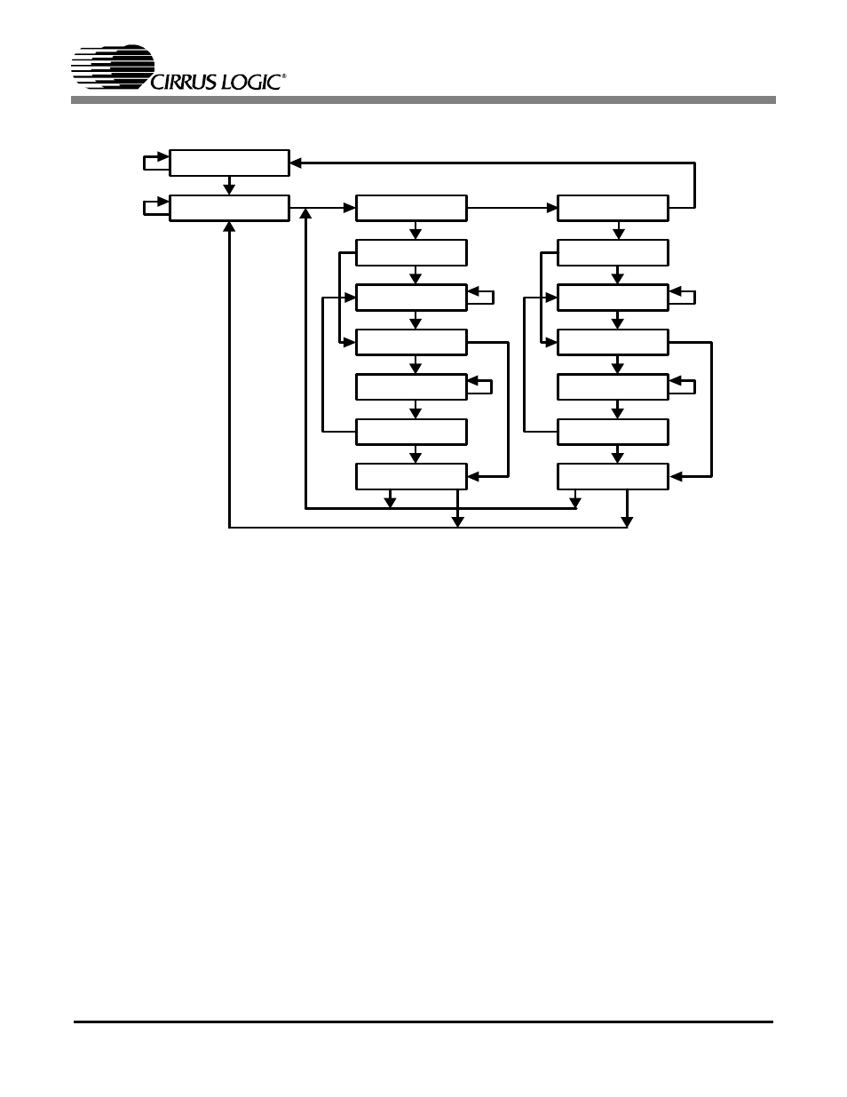
Page 45: 11 select-ir-scan, 12 capture-ir, 13 shift-ir, Figure 15. tap controller state diagram
CS61880
DS450PP3
45
16.1.8 Pause-DR
The pause state allows the test controller to tempo-
rarily halt the shifting of data through the current
test data register.
16.1.9 Exit2-DR
This is a temporary state. The test data register se-
lected by the current instruction retains its previous
value.
16.1.10 Update-DR
The Boundary Scan Register is provided with a
latched parallel output to prevent changes while
data is shifted in response to the EXTEST and
SAMPLE/PRELOAD instructions. When the TAP
controller is in this state and the Boundary Scan
Register is selected, data is latched into the parallel
output of this register from the shift-register path
on the falling edge of TCK. The data held at the
latched parallel output changes only in this state.
16.1.11 Select-IR-Scan
This is a temporary controller state. The test data
register selected by the current instruction retains
its previous state.
16.1.12 Capture-IR
In this controller state, the instruction register is
loaded with a fixed value of “01” on the rising edge
of TCK. This supports fault-isolation of the board-
level serial test data path.
16.1.13 Shift-IR
In this state, the shift register contained in the in-
struction register is connected between TDI and
TDO and shifts data one stage towards its serial
output on each rising edge of TCK.
1
0
Test-Logic-Reset
Run-Test/Idle
Select-DR-Scan
Capture-DR
Shift-DR
Exit1-DR
Pause-DR
Exit2-DR
Update-DR
Select- I R-Scan
Capture- IR
Shift- IR
Exit1- IR
Pause- IR
Exit2- IR
Update- IR
0
1
1
1
1
1
1
1
1
1
1
1
1
1
1
0
0
0
0
0
0
0
0
0
0
0
0
0
1
0
Figure 15. TAP Controller State Diagram