Cdb53l30, 5 performance plots – Cirrus Logic CDB53L30 User Manual
Page 20
20
DS963DB1
CDB53L30
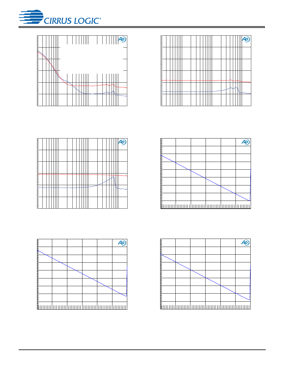
5 Performance Plots
Figure 5-17. THD+N (Relative) vs. Frequency,
Preamp Setting: 0 dB, –1 dBFS
Figure 5-18. THD+N (Relative) vs. Frequency,
Preamp Setting: +10 dB, –1 dBFS
Figure 5-19. THD+N (Relative) vs. Frequency,
Preamp Setting: +20 dB, –1 dBFS
Figure 5-20. THD+N (Relative) vs. Level, Preamp Setting: 0 dB,
PGA Setting: 0 dB, 1 kHz
Figure 5-21. THD+N (Relative) vs. Level, Preamp Setting: 0 dB,
PGA Setting: +12 dB, 1 kHz
Figure 5-22. THD+N (Relative) vs. Level,
Preamp Setting: +10 dB, PGA Setting: 0 dB, 1 kHz
G
%
N
N
N
N
N
+]
PGA Setting: +12 dB
PGA Setting: 0 dB
Note: The low-frequency distortion
is dominated by the MLCC Class II
DC blocking capacitor (0.1
F). To
reduce this distortion, reduce the
corner frequency by selecting a
larger cap, or choose a different cap
type such as film or MLCC Class I.
G
%
N
N
N
N
N
+]
PGA Setting: 0 dB
PGA Setting: +12 dB
G
%
N
N
N
N
N
+]
PGA Setting: +12 dB
PGA Setting: 0 dB
G
%
G%U
G
%
G%U
G
%
G%U
- CobraNet (147 pages)
- CS4961xx (54 pages)
- CS150x (8 pages)
- CS1501 (16 pages)
- CS1601 (2 pages)
- CS1601 (16 pages)
- CS1610 (16 pages)
- CRD1610-8W (24 pages)
- CRD1611-8W (25 pages)
- CDB1610-8W (21 pages)
- CS1610A (18 pages)
- CDB1611-8W (21 pages)
- CDB1610A-8W (21 pages)
- CDB1611A-8W (21 pages)
- CRD1610A-8W (24 pages)
- CRD1611A-8W (25 pages)
- CS1615 (16 pages)
- AN403 (15 pages)
- AN401 (14 pages)
- AN400 (15 pages)
- AN375 (27 pages)
- AN376 (9 pages)
- CRD1615-8W (22 pages)
- CRD1616-8W (23 pages)
- AN402 (14 pages)
- AN404 (15 pages)
- CRD1615A-8W (21 pages)
- CS1615A (16 pages)
- CS1630 (56 pages)
- AN374 (35 pages)
- AN368 (80 pages)
- CRD1630-10W (24 pages)
- CRD1631-10W (25 pages)
- CS1680 (16 pages)
- AN405 (13 pages)
- AN379 (31 pages)
- CRD1680-7W (31 pages)
- AN335 (10 pages)
- AN334 (6 pages)
- AN312 (14 pages)
- AN Integrating CobraNet into Audio Products (16 pages)
- CobraNet Audio Routing Primer (9 pages)
- Bundle Assignments in CobraNet Systems (3 pages)
- CS2300-01 (3 pages)
- CS2000-CP (38 pages)