4 cs53l30 tdm tab, Section 4.3.4, Describ – Cirrus Logic CDB53L30 User Manual
Page 15: Cdb53l30
15
DS963DB1
CDB53L30
4.3 Using the FlexGUI Tabs
4.3.4
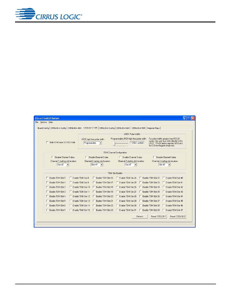
CS53L30 TDM Tab
The “CS53L30-1 TDM” and “CS53L30-2 TDM” tabs contain the controls for configuring the CS53L30 TDM output. These
controls apply only when the ASP Mode is configured for TDM on the “CS53L30 Config” tab.
•
Shift TDM frame 1/2 SCLK left—Configures the start offset of TDM data after a rising edge of LRCK/FSYNC.
•
LRCK Pulse Width—Configures the LRCK/FSYNC high time in TDM mode. The pulse width can be fixed to 50%
duty cycle or configured for any number of SCLK cycles. The high-level GUI allows the user to select between 1
and 8 SCLK cycles as the programmable high time. To configure the CS53L30 for a programmable high time of
greater than 8 SCLK cycles, the user should write directly to the LRCK_TPWH field in registers 0x1B and 0x1C in
the appropriate CS53L30 register tab.
•
TDM Channel Configuration—Enables TDM output from each of the four ADC channels and configures the
channel’s starting TDM slot location.
•
TDM Slot Enable—Determines into which of the 48 available TDM time slots the CS53L30 can load data. During
time slots which are not enabled, the ASP1_SDOUT output pin is Hi-Z.
•
Refresh—Reads all registers in all devices and updates the values in the FlexGUI.
•
Reset CS53L30-1—Sends a reset pulse to CS53L30 #1.
•
Reset CS53L30-2—Sends a reset pulse to CS53L30 #2.
Figure 4-7. The “CS53L30 TDM” Tab