Test bit stream generator, 1 pin descriptions, 2 tbs architecture – Cirrus Logic CS5378 User Manual
Page 60: 3 tbs configuration, Pin descriptions, Tbs architecture, Tbs configuration, Figure 36. test bit stream generator block diagram, Cs5378
CS5378
DS639F3
60
17. TEST BIT STREAM GENERATOR
The CS5378 test bit stream (TBS) generator creates
sine wave
ΔΣ bit stream data to drive an external
test DAC. The TBS digital output can also be in-
ternally connected to the MDATA inputs for loop-
back testing of the digital filter.
17.1 Pin Descriptions
TBSDATA - Pin 8
Test bit stream 1-bit
ΔΣ data output.
MCLK - Pin 11
Test bit stream clock output.
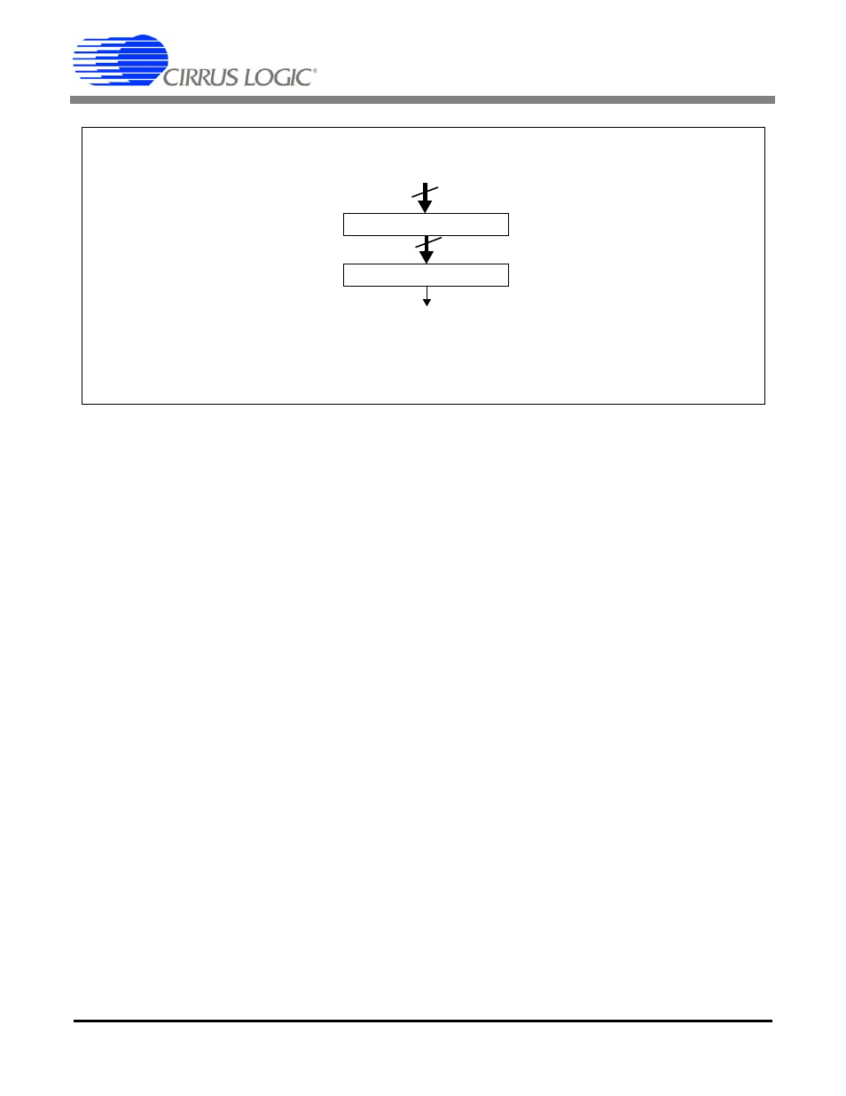
17.2 TBS Architecture
The test bit stream generator consists of a data in-
terpolator and a digital
ΔΣ modulator. It receives
periodic 24-bit data from the digital filter to create
a 1-bit
ΔΣ data output on the TBSDATA pin.
The TBS input data from the digital filter is scaled
by the TBSGAIN register (0x2B). Maximum sta-
ble amplitude is 0x04FFFF, with 0x04B000 ap-
proximately full scale for the CS5373A test DAC.
The full scale 1-bit
ΔΣ output from the TBS gener-
ator is defined as 25% minimum and 75% maxi-
mum one’s density.
17.3 TBS Configuration
Configuration options for the TBS generator are set
through the TBSCFG register (0x2A). Gain scal-
ing of the TBS generator output is set by the TB-
SGAIN register (0x2B).
Interpolation Factor - INTP[7:0]
Selects how many times the interpolator uses a data
point when generating the output bit stream. Inter-
polation is zero based and represents one greater
than the programmed register value.
Output Rate - RATE[2:0]
Selects the TBSDATA output rate.
Synchronization - TSYNC
Enables synchronization of the TBS output phase
to the MSYNC signal.
Loopback - LOOP
Enables digital loopback from the TBS output to
the MDATA inputs.
Run - RUN
Enables the test bit stream generator.
Digital
ΔΣ Modulator
24-bit
1-bit
TBSDATA
Digital Filter
TBSGAIN Register
24-bit
Figure 36. Test Bit Stream Generator Block Diagram
Data Bus