Gain and offset correction, 1 gain correction, 2 offset correction – Cirrus Logic CS5378 User Manual
Page 56: Gain correction, Offset correction, Figure 32. gain and offset correction, Cs5378
CS5378
DS639F3
56
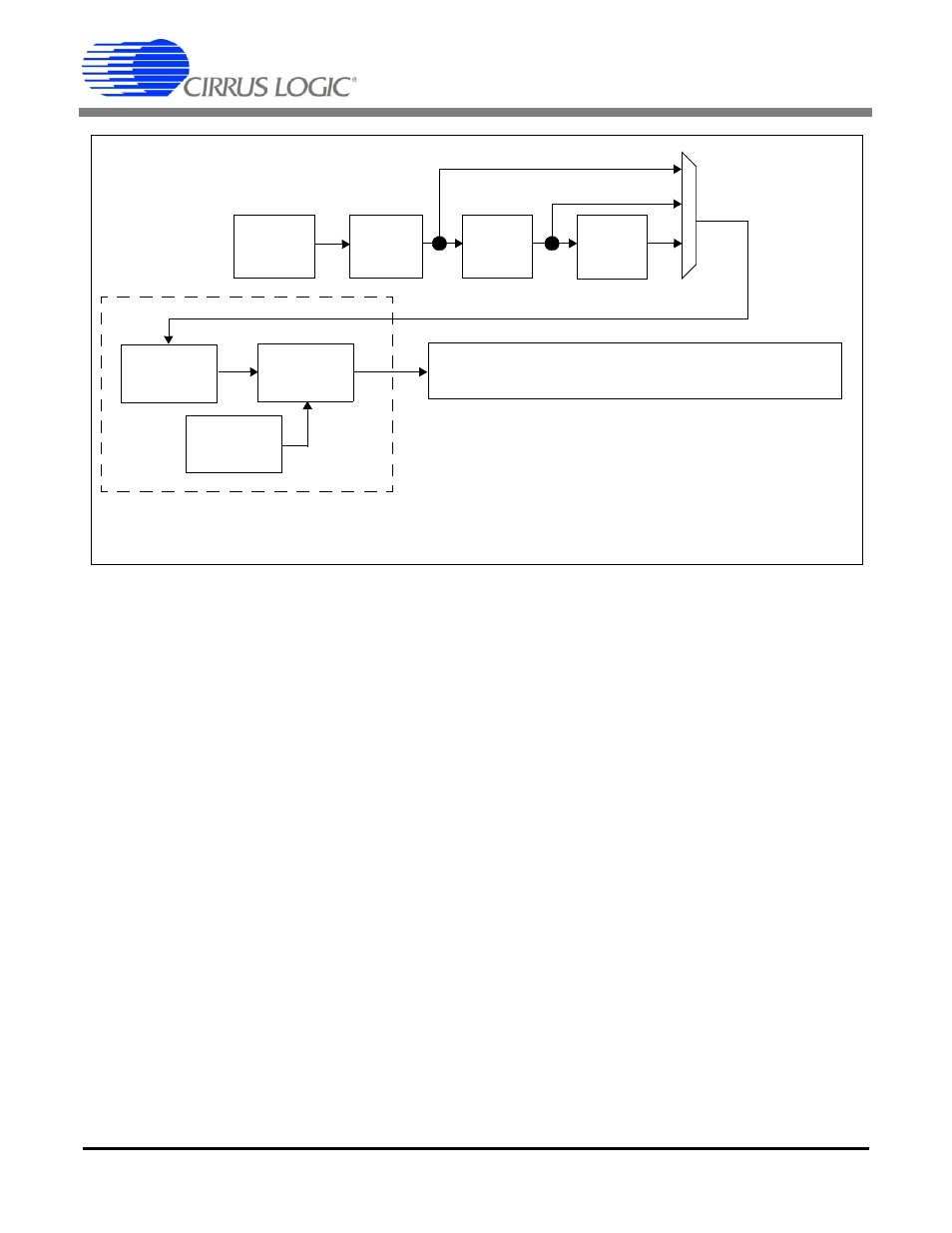
15. GAIN AND OFFSET CORRECTION
The CS5378 digital filter can apply gain and offset
corrections to the measurement data. Also, an off-
set calibration algorithm can automatically calcu-
late the offset correction value.
A gain correction value is written to the GAIN reg-
isters (0x21), while an offset correction value is
written to the OFFSET register (0x25). Gain and
offset corrections are enabled by the USEGR and
USEOR bits in the FILTCFG register (0x20).
When enabled, the offset calibration algorithm will
automatically calculate an offset correction value
and write it into the OFFSET register. Offset cali-
bration is enabled by writing the EXP and ORCAL
bits in FILTCFG.
15.1 Gain Correction
Gain correction in the CS5378 normalizes sensor
gain in multi-sensor networks. It requires an exter-
nally calculated correction value to be written into
the GAIN register (0x21).
A gain correction value is 24-bit two’s complement
with unity gain defined as full scale, 0x7FFFFF.
Gain correction always scales to a fractional value,
and can never gain the digital filter data greater
than one.
Output Value = Data * (GAIN / 0x7FFFFF)
Unity Gain: GAIN = 0x7FFFFF
50% Gain: GAIN = 0x3FFFFF
Zero Gain: GAIN = 0x000000
Once the GAIN register is written, the USEGR bit
in the FILTCFG register enables gain correction.
15.2 Offset Correction
Offset correction in the CS5378 cancels the DC
bias of a measurement channel by subtracting the
value in the OFFSET register (0x25) from the dig-
ital filter output data word.
An offset correction value is 24-bit two’s comple-
ment with a maximum positive value of 0x7FFFFF,
Figure 32. Gain and Offset Correction
FIR
IIR
Filters
Filter
Output to High Speed Serial Data Port (SD Port)
Offset
Correction
Output Rate 4000 SPS ~ 1 SPS
SINC
Filter
MDI Input
512 kHz
Correction
Gain
Offset
Calibration