System design with cs5378, 1 power supplies, 2 reset control – Cirrus Logic CS5378 User Manual
Page 18: 3 pll and clock generation, Power supplies, Reset control, Pll and clock generation, Figure 9. single-channel system block diagram, Cs5378
CS5378
DS639F3
18
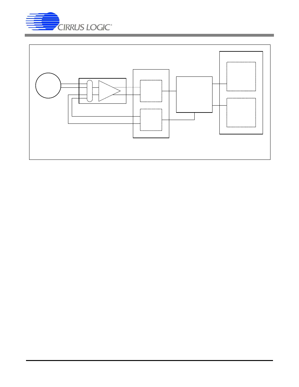
3. SYSTEM DESIGN WITH CS5378
Figure 9 illustrates a simplified block diagram of
the CS5378 in a single channel measurement sys-
tem.
A differential sensor is connected through the
CS3301A/02A differential amplifiers to the
CS5373A
ΔΣ modulator, where analog to digital
conversion occurs. The modulator’s 1-bit output
connects to the CS5378 MDATA input, where the
oversampled
ΔΣ data is decimated and filtered to
24-bit output samples at a programmed output rate.
These output samples are buffered into an 8-deep
data FIFO and then passed to the system telemetry.
System self tests are performed by connecting the
CS5378 test bit stream (TBS) generator to the
CS5373A test DAC. Analog tests drive differential
signals from the CS5373A test DAC into the mul-
tiplexed inputs of the CS3301A/02A amplifiers or
directly to the differential sensor. Digital loopback
tests internally connect the TBS digital output di-
rectly to the CS5378 modulator input.
3.1 Power Supplies
The system shown in Figure 9 typically operates
from a
±
2.5 V analog power supply and a 3.3 V
digital power supply. The CS5378 logic core can
be powered from 2.5 V to minimize power con-
sumption, if required.
3.2 Reset Control
System reset is required only for the CS5378 de-
vice, and is a standard active low signal that can be
generated by a power supply monitor or microcon-
troller. Other system devices default to a power-
down state when the CS5378 is reset.
3.3 PLL and Clock Generation
A PLL is included on the CS5378 to generate an in-
ternal 32.768 MHz master clock from a
1.024 MHz, 2.048 MHz, or 4.096 MHz standard
clock or Manchester encoded input. Clock inputs
for other system devices are driven by clock out-
puts from the CS5378.
ΔΣ
Modulator
Test
DAC
Digital Filter
AMP
Differential
Sensor
M
U
X
μController
or
Configuration
EEPROM
System
Telemetry
CS3301A
CS3302A
CS5378
CS5373A
Figure 9. Single-Channel System Block Diagram