7 channel a pga control - address 08h, 1 channel a pga gain (bits 5:0), Table 10. example gain and attenuation settings – Cirrus Logic CS5346 User Manual
Page 31: 8 adc input control - address 09h, 1 pga soft ramp or zero cross enable (bits 4:3), Channel a pga control, Pg. 31, Cs5346
DS861PP3
31
CS5346
7.7
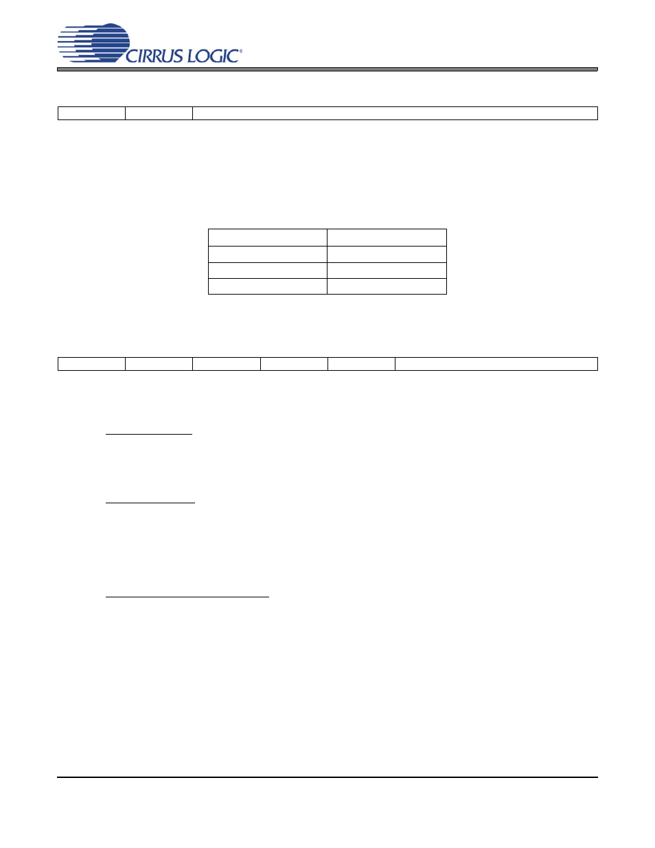
Channel A PGA Control - Address 08h
7.7.1
Channel A PGA Gain (Bits 5:0)
Function:
Sets the gain or attenuation for the ADC input PGA stage. The gain may be adjusted from -12 dB to
+12 dB in 0.5 dB steps. The gain bits are in two’s complement with the Gain0 bit set for a 0.5 dB step.
Register settings outside of the ±12 dB range are reserved and must not be used. See
for ex-
ample settings.
7.8
ADC Input Control - Address 09h
7.8.1
PGA Soft Ramp or Zero Cross Enable (Bits 4:3)
Function:
Soft Ramp Enable
Soft Ramp allows level changes, both muting and attenuation, to be implemented by incrementally ramp-
ing, in 1/8 dB steps, from the current level to the new level at a rate of 1 dB per 8 left/right clock periods.
Zero Cross Enable
Zero Cross Enable dictates that signal-level changes, either by attenuation changes or muting, will occur
on a signal zero crossing to minimize audible artifacts. The requested level change will occur after a time-
out period between 512 and 1024 sample periods (10.7 ms to 21.3 ms at 48 kHz sample rate) if the signal
does not encounter a zero crossing. The zero cross function is independently monitored and implemented
for each channel. See
.
Soft Ramp and Zero Cross Enable
Soft Ramp and Zero Cross Enable dictate that signal-level changes, either by attenuation changes or mut-
ing, will occur in 1/8 dB steps and be implemented on a signal zero crossing. The 1/8 dB level change will
occur after a time-out period between 512 and 1024 sample periods (10.7 ms to 21.3 ms at 48 kHz sam-
ple rate) if the signal does not encounter a zero crossing. The zero cross function is independently mon-
itored and implemented for each channel. See
7
6
5
4
3
2
1
0
Reserved
Reserved
Gain5
Gain4
Gain3
Gain2
Gain1
Gain0
Gain[5:0]
Setting
101000
-12 dB
000000
0 dB
011000
+12 dB
Table 10. Example Gain and Attenuation Settings
7
6
5
4
3
2
1
0
Reserved
Reserved
Reserved
PGASoft
PGAZero
Sel2
Sel1
Sel0