2 master mode, Figure 8. master mode clocking, 3 slave mode – Cirrus Logic CS5346 User Manual
Page 20: Table 3. slave mode serial bit clock ratios, 3 high-pass filter and dc offset calibration, Figure 8.master mode clocking, Cs5346
20
DS861PP3
CS5346
5.2.2
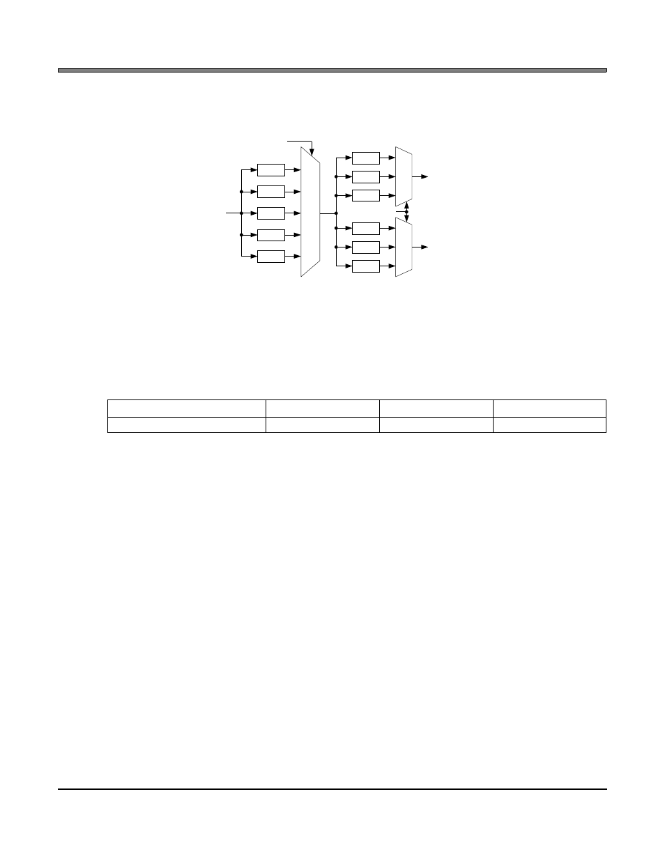
Master Mode
As a clock master, LRCK and SCLK will operate as outputs. LRCK and SCLK are internally derived from
MCLK with LRCK equal to Fs and SCLK equal to 64 x Fs as shown in
.
5.2.3
Slave Mode
In Slave Mode, SCLK and LRCK operate as inputs. The Left/Right clock signal must be equal to the sam-
ple rate, Fs, and must be synchronously derived from the supplied master clock, MCLK.
The serial bit clock, SCLK, must be synchronously derived from the master clock, MCLK, and be equal to
128x, 64x or 48x Fs, depending on the desired speed mode. Refer to
5.3
High-Pass Filter and DC Offset Calibration
When using operational amplifiers in the input circuitry driving the CS5346, a small DC offset may be driven
into the A/D converter. The CS5346 includes a high-pass filter after the decimator to remove any DC offset
which could result in recording a DC level, possibly yielding clicks when switching between devices in a mul-
tichannel system.
The high-pass filter continuously subtracts a measure of the DC offset from the output of the decimation
filter. If the HPFFreeze bit (See
“High-Pass Filter Freeze (Bit 1)” on page 29.
) is set during normal operation,
the current value of the DC offset for the each channel is frozen and this DC offset will continue to be sub-
tracted from the conversion result. This feature makes it possible to perform a system DC offset calibration
by:
1. Running the CS5346 with the high-pass filter enabled until the filter settles. See the Digital Filter Char-
acteristics section for filter settling time.
2. Disabling the high-pass filter and freezing the stored DC offset.
A system calibration performed in this way will eliminate offsets anywhere in the signal path between the
calibration point and the CS5346.
Single-Speed
Double-Speed
Quad-Speed
SCLK/LRCK Ratio
48x, 64x, 128x
48x, 64x
48x, 64x
Table 3. Slave Mode Serial Bit Clock Ratios
ч256
ч128
ч64
ч4
ч2
ч1
00
01
10
00
01
10
LRCK
SCLK
000
001
010
ч1
ч1.5
ч2
011
100
ч3
ч4
MCLK
FM Bits
MCLK Freq Bits
Figure 8. Master Mode Clocking