Analog hardware description, 1 analog inputs, 1 line inputs – Cirrus Logic CS4205 User Manual
Page 64: 2 cd input, Figure 26. differential 2 vrms cd input, Figure 27. differential 1 vrms cd input, 1 line inputs 12.1.2 cd input, Cs4205, Cd input signal
CS4205
64
DS489PP4
12. ANALOG HARDWARE
DESCRIPTION
The analog input section consists of four stereo
line-level inputs (LINE_L/R, CD_L/GND/R,
VIDEO_L/R, and AUX_L/R), two selectable
mono microphone inputs (MIC1 and MIC2), and
two mono inputs (PC_BEEP and PHONE). The an-
alog output section consists of a mono output
(MONO_OUT) and a stereo line-level output
(LINE_OUT_L/R). This section describes the ana-
log hardware needed to interface with these pins.
The designs presented in this section are compliant
with Chapter 17 of Microsoft’s
®
PC 99 System De-
sign Guide [7] (referred to as PC 99) and Chapter
11 of Microsoft’s
®
PC 2001 System Design Guide
[8] (referred to as PC 2001). For information on
EMI reduction techniques refer to the application
note AN165: CS4297A/CS4299 EMI Reduction
Techniques [5].
12.1
Analog Inputs
All analog inputs to the CS4205, including
CD_GND, should be capacitively coupled to the
input pins. Unused analog inputs should be tied to-
gether and connected through a capacitor to analog
ground or tied to the Vrefout pin directly. The max-
imum allowed voltage for analog inputs, except the
microphone input, is 1 V
RMS
. The maximum al-
lowed voltage for the microphone input depends on
the selected boost setting.
12.1.1
Line Inputs
Figure 25 shows circuitry for a line-level stereo in-
put. Replicate this circuit for the Video and Aux in-
puts. This design attenuates the input by 6 dB,
bringing the signal from the PC 99 specified
2 V
RMS
, to the CS4205 maximum allowed 1 V
RMS
.
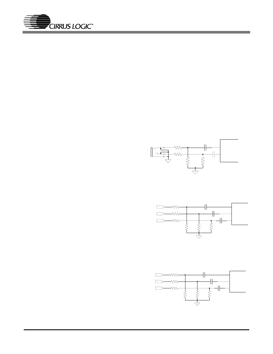
12.1.2
CD Input
The CD line-level input has an extra pin,
CD_GND, providing a pseudo-differential input
for both CD_L and CD_R. This pin takes the
common-mode noise out of the CD inputs when
connected to the CD analog source ground. Follow-
ing the reference designs in Figure 26 and
Figure 27 provides extra attenuation of common
mode noise coming from the CD-ROM drive,
thereby producing a higher quality signal. One per-
cent resistors are recommended since closely
matched resistor values provide better com-
mon-mode attenuation of unwanted signals. The
circuit shown in Figure 26 can be used to attenuate
a 2 V
RMS
CD input signal by 6 dB. The circuit
shown in Figure 27 can be used for a 1 V
RMS
CD
input signal.
LINE_IN_R
LINE_IN_L
6.8 k
Ω
1.0
µ F
1.0
µ F
AGND
AGND
6.8 k
Ω
6.8 k
Ω
6.8 k
Ω
Figure 25. Line Input (Replicate for Video and AUX)
(All resistors 1%)
6.8 k
Ω
CD_L
CD_COM
CD_R
1.0
µF
CD_L
CD_R
CD_GND
6.8 k
Ω
1.0
µF
3.4 k
Ω
6.8 k
Ω
2.2
µF
3.4 k
Ω
6.8 k
Ω
AGND
Figure 26. Differential 2 V
RMS
CD Input
100
Ω
CD_L
CD_COM
CD_R
1.0
µF
CD_L
CD_R
CD_GND
100
Ω
1.0
µF
100
Ω
47 k
Ω
2.2
µF
47 k
Ω
47 k
Ω
AGND
Figure 27. Differential 1 V
RMS
CD Input