Ac-link frame definition, Figure 14. ac-link input and output framing, Tailed in section 4, ac-link frame definition – Cirrus Logic CS4205 User Manual
Page 19: Cs4205
CS4205
DS489PP4
19
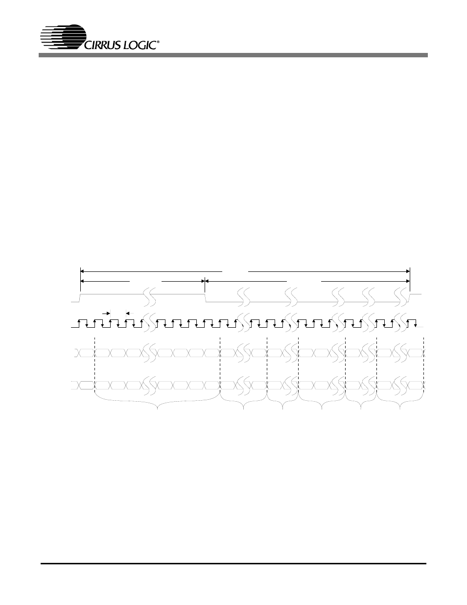
4. AC-LINK FRAME DEFINITION
The AC-link is a bi-directional serial port with data
organized into frames consisting of one 16-bit and
twelve 20-bit time-division multiplexed slots.
Slot 0 is a special reserved time slot containing
16-bits which are used for AC-link protocol infra-
structure. Slots 1 through 12 contain audio or con-
trol/status data. Both the serial data output and
input frames are defined from the controller per-
spective, not from the CS4205 perspective.
The controller synchronizes the beginning of a
frame with the assertion of the SYNC signal.
Figure 14 shows the position of each bit location
within the frame. The first bit position in a new se-
rial data frame is F0 and the last bit position in the
serial data frame is F255. When SYNC goes active
(high) and is sampled active by the CS4205 (on the
falling edge of BIT_CLK), both devices are syn-
chronized to a new serial data frame. The data on
the SDATA_OUT pin at this clock edge is the final
bit of the previous frame’s serial data. On the next
rising edge of BIT_CLK, the first bit of Slot 0 is
driven by the controller on the SDATA_OUT pin.
On the next falling edge of BIT_CLK, the CS4205
latches this data in as the first bit of the frame.
20.8
µs
(48 kHz)
Tag Phase
Data Phase
12.288 MHz
81.4 ns
SYNC
BIT_CLK
SDATA_OUT
SDATA_IN
F0
F1
F2
F16
F15
F14
F13
F12
F35
F56
F76
D19
F255
Valid
Frame
Slot 1
Valid
0
R/W
0
WD15
F36
F57
D19
D18
D19
D19
D18
D19
RD15
0
0
0
0
F0
F1
F2
F16
F15
F14
F13
F12
F35
F56
F76
F255
F36
F57
F255
F255
0
0
GPIO
INT
F96
F96
D19
Slot 0
Slot 1
Slot 2
Slot 3
Slot 4
Slots 5-12
Slot 2
Valid
Slot 1
Valid
Slot 2
Valid
Codec
Ready
0
Slot 12
Valid
Codec
ID1
Codec
ID0
Slot 12
Valid
GPIO
INT
Bit Frame Position:
Bit Frame Position:
Figure 14. AC-link Input and Output Framing