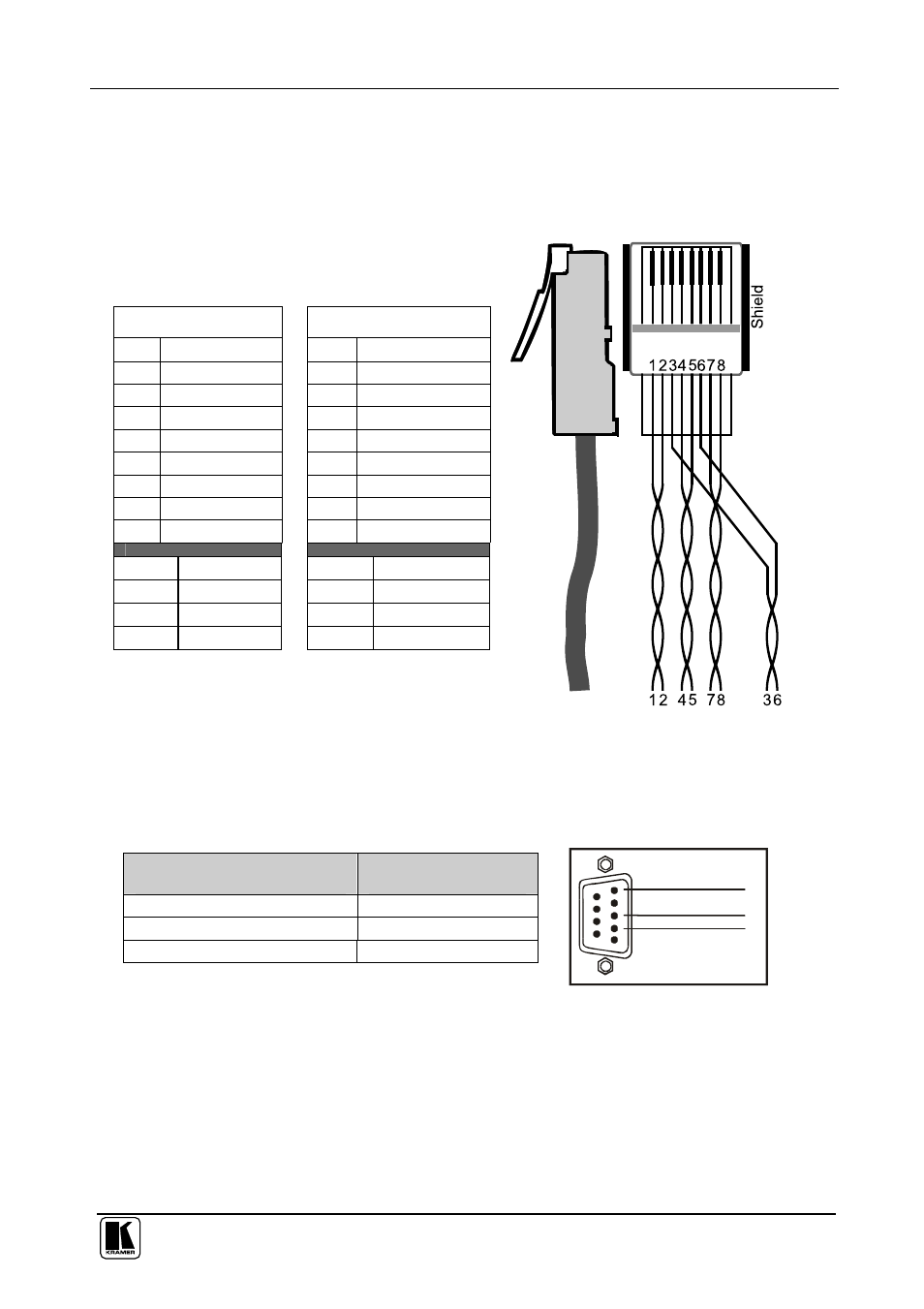
Table 11: cat 5 pinout, Figure 15: cat 5 pinout – Kramer Electronics TP-107AV User Manual
Page 22
Configuring a TP-107V / TP-107AV System
19
5.3 Wiring the CAT 5 LINE IN / LINE OUT RJ-45 Connectors
Table 11 and Figure 15 define the STP CAT 5 PINOUT, using a straight
pin-to-pin
cable with RJ-45 connectors:
Table 11: CAT 5 PINOUT
EIA /TIA 568A
EIA /TIA 568B
PIN Wire Color
PIN
Wire Color
1
Green / White
1
Orange / White
2
Green
2
Orange
3
Orange / White
3
Green / White
4
Blue
4
Blue
5
Blue / White
5
Blue / White
6
Orange
6
Green
7
Brown / White
7
Brown / White
8
Brown
8
Brown
Pair 1
4 and 5
Pair 1
4 and 5
Pair 2
3 and 6
Pair 2
1 and 2
Pair 3
1 and 2
Pair 3
3 and 6
Pair 4
7 and 8
Pair 4
7 and 8
Figure 15: CAT 5 PINOUT
5.4 Connecting the RS-232 Port
The RS-232 9-pin D-sub connector port is defined in Table 12 and Figure 16:
Table 12: RS-232 PINOUT Connection
Connect this PIN on the
Terminal Block Connector:
To this PIN on the 9-pin
D-sub Connector
Tx
PIN 2
Rx
PIN 3
GND
PIN 5
RS-232 PINOUT
Rx
GND
1
2
3
4
5
6
7
8
9
Tx
Figure 16: RS-232 PINOUT
Connection