Kramer Electronics TP-107AV User Manual
Page 15
KRAMER: SIMPLE CREATIVE TECHNOLOGY
Your Line Transmitters and Presentation Controllers
12
4.2.2
Your TP-122 XGA / Audio Line Receiver
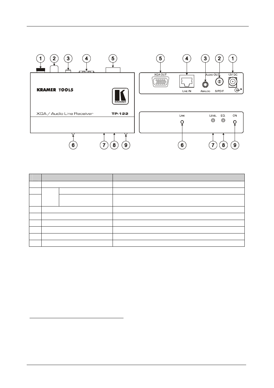
Figure 7 and Table 7 define the
TP-122 XGA / Audio Line Receiver:
Figure 7: TP-122 XGA / Audio Line Receiver
Table 7: TP-122 XGA / Audio Line Receiver Features
#
Feature
Function
1
12V DC
+12V DC connector for powering the unit
2
S/PDIF RCA connector
Connects to the digital audio acceptor
3
A
U
D
IO
O
U
T
ANALOG 3.5mm Mini
Jack
Connects to the analog audio acceptor
4
LINE IN RJ-45 Connector
Connects to
1
the TP-121 or the TP-104
2
5
XGA OUT HD15F Connector
Connects to the XGA acceptor
6
LINK LED
Illuminates when receiving the correct input signal
7
LEVEL Trimmer
Adjusts
4
the output signal level
8
EQ.
3
Trimmer
Adjusts
4
the cable compensation equalization level
9
ON LED
Illuminates when receiving power
1 Using an STP CAT 5 cable with RJ-45 connectors at both ends (the PINOUT is defined in Table 11 and Figure 15)
2 The TP-104 does not accept the audio signals
3 Degradation and VGA/XGA signal loss can result from using long cables (due to stray capacitance), sometimes leading to a
total loss of sharpness in high-resolution signals
4 Use a screwdriver to carefully rotate the trimmer, adjusting the appropriate level