Kramer Electronics VS-808YC User Manual
Page 9
KRAMER: SIMPLE CREATIVE TECHNOLOGY
Your VS-808YC 8x8 s-Video / Audio Matrix Switcher
6
Table 2: Rear Panel VS-808YC 8x8 s-Video / Audio Matrix Switcher Features
#
Feature
Function
15
AUDIO INPUTS
Terminal Block
Connectors
Connect to the balanced stereo audio sources (from 1 to 8)
16
VIDEO INPUTS
4-pin
Connectors
Connects to the s-Video sources (from 1 to 8)
17
VIDEO OUTPUTS
4-pin
Connectors
Connects to the s-Video acceptors (from 1 to 8)
18
DIP-switches
DIP-switches for setup of the unit (1, 2, 3 and 4 are for setting the
Machine #; 8 is for RS 485 Termination)
19
AUDIO OUTPUTS
Terminal
Block Connectors
Connect to the balanced stereo audio acceptors (from 1 to 8)
20
RS-232
9-pin D-sub Port
Connects to the PC or the Remote Controller
21
REMOTE IR
Opening
1
Connects to an external IR receiver unit for controlling the machine via
an IR remote controller instead of using the front panel IR receiver
2
22
FLASH PROG
Button
Push in
3
for “Program” to upgrade to the latest Kramer firmware
(see section 9), or release for Normal (the factory default)
23
RS-485
Terminal Block Port
Pin G is for Ground connection; Pins B (-) and A (+) are for RS 485
24
Power Connector with Fuse
AC connector enabling power supply to the unit
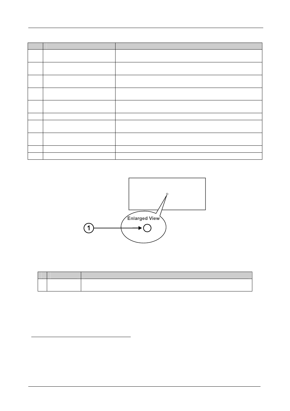
Figure 2 and Table 3 define the Flash button on the underside of the
VS-808YC:
Figure 2: VS-808YC Underside Flash Program Button
Table 3: VS-808YC Underside Flash Program Button
#
Feature
Function
1 Flash Program
Reset Button
Push in
4
for “Reset” (see section 9), or release for Normal (the factory default)
1 Covered by a cap. The 3.5mm connector at the end of the internal IR connection cable fits through this opening
2 Optional. Can be used instead of the front panel (built-in) IR receiver to remotely control the machine (only if the internal
IR connection cable has been installed)
3 Using a thin screwdriver if required
4 Using a screwdriver if required