Kramer Electronics VS-808YC User Manual
Page 17
KRAMER: SIMPLE CREATIVE TECHNOLOGY
Connecting the VS-808YC
14
6.5 Setting the DIP-switches
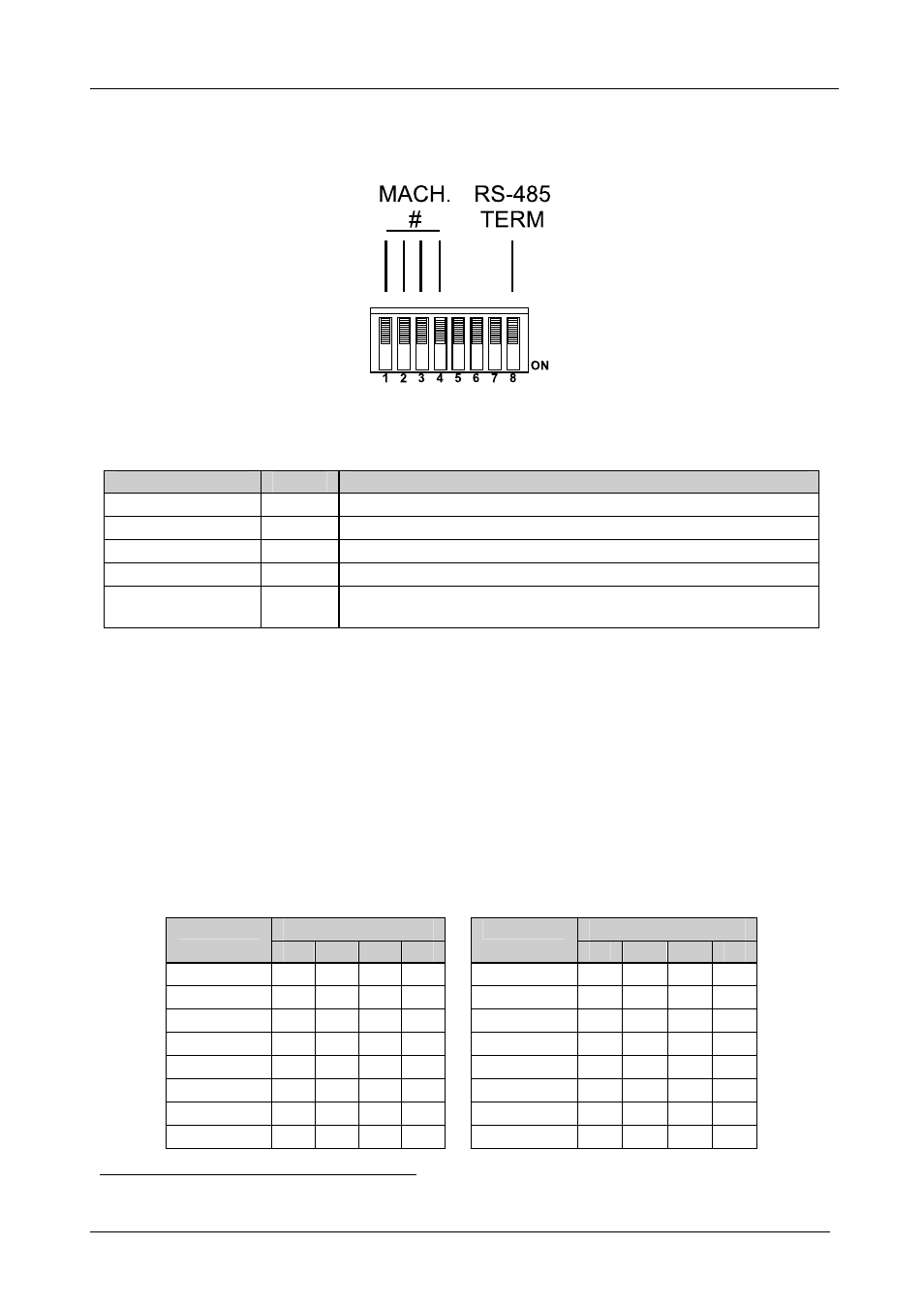
Figure 9 illustrates the factory default DIP-switches:
Figure 9: DIP-switch Settings
Table 4: DIP-switch Settings
Function
DIPS
Description
Machine #
1, 2, 3, 4 Determines the position of a unit in the sequence (see section 6.5.1)
Reserved
5
OFF
Reserved
6
OFF
Reserved
7
OFF
RS-485 Termination 8
ON for RS-485 Line Termination with 120 ;
OFF for no RS-485 Line Termination
6.5.1
Setting the MACHINE #
The MACHINE # determines the position of a
VS-808YC unit, specifying
which
VS-808YC unit is being controlled when several VS-808YC units
connect to a PC or serial controller. Set the MACHINE # on a
VS-808YC unit
via DIPS 1, 2, 3 and 4, according to Table 5.
When using a stand-alone
VS-808YC unit, set the MACHINE # to 1. When
connecting more than one
VS-808YC unit, set the first machine (the Master)
that is closest to the PC, as MACHINE # 1
1
.
Table 5: Machine # DIP-switch Settings
DIP-Switch
DIP-Switch
MACHINE #
1
2
3
4
MACHINE #
1
2
3
4
1
Master
OFF OFF OFF OFF
9
ON OFF OFF OFF
2
OFF OFF OFF ON
10
ON OFF OFF ON
3
OFF OFF ON OFF
11
ON OFF ON OFF
4
OFF OFF ON ON
12
ON OFF ON ON
5
OFF ON OFF OFF
13
ON ON OFF OFF
6
OFF ON OFF ON
14
ON ON OFF ON
7
OFF ON ON OFF
15
ON ON ON OFF
8
OFF ON ON ON
16
ON ON ON ON
1 Set the DIP-switches to OFF