2 controlling the vp-88k via rs-485, Controlling the vp-88k via rs-485, Figure 22: dip-switch setting for machine 2 – Kramer Electronics VP-88K User Manual
Page 30
KRAMER: SIMPLE CREATIVE TECHNOLOGY
Controlling the VP-88K
26
1. Connect the video sources and acceptors, the appropriate audio sources and
acceptors, and the power cord to each VP-88K.
2. Connect the RS-232 port on the first VP-88K to the PC (see
Section 6.2
3. Set the Machine # to 1 of the unit connected to the PC.
4. Set Machine 1 RS-485 termination to On (see
Section 6.5
5. Set the Machine # on all VP-88K units other than Machine 1 to a unique
number between 2 and 16 (see
Section 6.5
6. Set the termination on all VP-88K units other than Machine 1 to Off.
).
7. Interconnect the RS-485 bus on all VP-88K units:
From the RS-485 connector on the first VP-88K unit, to the RS-485 port
on the second VP-88K unit, and so on. Up to sixteen VP-88K units can
be connected.
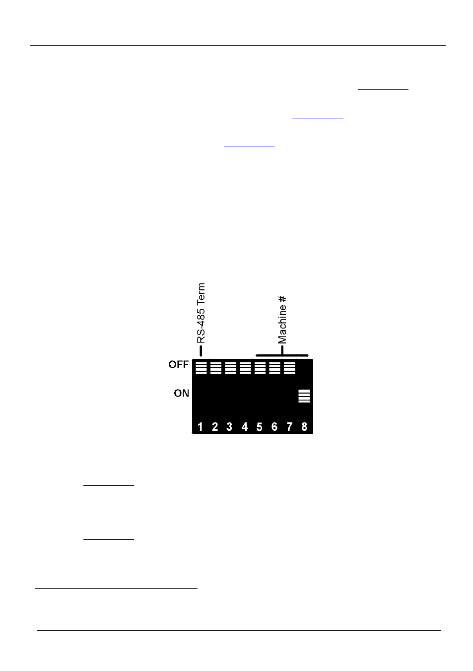
8.2 Controlling the VP-88K via RS-485
To control up to fifteen VP-88K units via an RS-485 controller or a PC
equipped with an RS-485 interface
:
Figure 22: DIP-switch Setting for Machine 2
1. Connect up to 15 VP-88K devices to the controller via RS-485 (see
Section 6.3
2. Connect the video sources and acceptors, the appropriate audio sources and
acceptors, and the power cord to each VP-88K unit.
3. Set the Machine number on the first VP-88K to be Machine 2 (see
Section 6.5
4. Terminate the RS-485 line on both the Controller/PC and on the last VP-88K
(set DIP-switch 1 to ON).
1 Switch OFF the power on each device before connecting it to your VP-88K. After connecting your VP-88K, switch on its power and
then switch on the power on each device